4. Feeding the Antenna
So far, we have described a 20 meter dipole that is 40 feet up, built using 14 AWG wire. But we haven't yet provided any source to feed the dipole!
- Element Inspector
To give this wire element an excitation, double-click on the spreadsheet cell that has the number "1" under the # column. This brings up the Element Inspector window for this wire element.
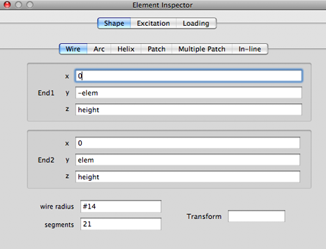
It is now obvious where the formulas that we have been editing earlier are hiding!
You can edit the formulas in the inspector window instead of editing them in the Cell Editor. In fact, the only way to manipulate formulas for the more complex shapes such as arcs and helixes is to edit them in the inspector window. The Cell Editor that we had described in the previous chapter is just a shortcut that you can use with the wire type element (the most often used shape for amateur HF antennas).
Another way to open the Element Inspector window is to select the row of the element in the spreadsheet and then choose Open Element Inspector in the Window menu.
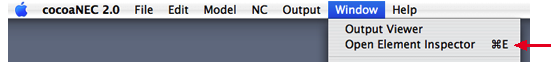
You can also select the row in the spreadsheet and use the Command-E keyboard shortcut for an even faster way to bring up the Element Inspector for a wire.
- Excitation
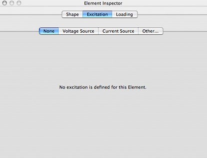
You will find an Excitation button in addition to the Shape tab button in the Element Inspector window.
This is how you tell cocoaNEC to put a feed point on a wire. (The Loading button allows you to insert a load such as a inductor or a resistor into the element.)
When you select Excitation, as seen below, you will notice that there is no excitation defined for the wire. Many if not most, wires in an antenna are not associated to an excitation. For example, a monoband Yagi-Uda antenna may have numerous elements, but it has only a single feed point (excitation).
To proceed with our example, select the Voltage Source tab inside the Excitation view instead of the None tab. You should now see this:
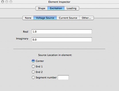
The default voltage source has a real part of 1 volt and no relative phase angle. The source is placed at the center of the wire, which is what we want for our dipole.
If you remember, we had previously set the number of segments for this wire to 21, which is an odd number. This ensures that the dipole's feedpoint is at the precise middle of the wire element. If the number of segments is an even number, the feed point cannot be placed at the precise center of the wire.
With proper selection of the radio buttons, you can place the excitation at ether end of the wire instead of at the center. You can also place the excitation at any specific segment number. In the case of our 21 segment wire, this number can be between 1 and 21 -- this is one way you can offset feed the dipole.
With the Excitation selected to use a voltage source at the center of the wire, we are now finished with specifying the feed point for the dipole.
You could use a current source instead of a voltage source. Current sources are useful for modeling phased arrays, where the feedpoint currents (and not voltages) have to maintain certain phase relationships. Notice that the Real and Imaginary fields in the sources can be formulas. So you could use a real part of cosd(60) and an imaginary part of sind(60) to generate a source that has a 60 degree phase shift.
You can now close the Element Inspector window.
Next: Running the Model...