Dual RTTY Interface
Please note that the Dual RTTY Interface is deprecated. It is kept around but no new functions will be added directly to it. As new demodulators are developed, the Dual RTTY Interface may not be able to use them. Please use the Wideband RTTY Interface instead.
Figure 9 shows the Dual RTTY Interface. Please familiarize yourself with the Basic RTTY Interface of cocoaModem before reading the rest of this section.
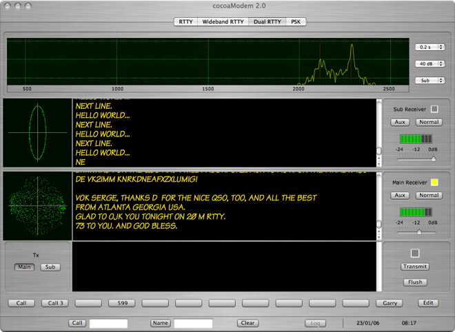
Figure 9 - Dual RTTY
Interface
Dual RTTY Receivers
Notice that there are two separate receiver sections below
a spectrum display. Each of these receivers is a completely
independent copy of the receiver in the basic RTTY
Interface of cocoaModem and each one comes with its own
configuration section in the Config Panel.
Since these are independent receivers, you will need to
configure both of the receivers before using the Dual RTTY
Interface. The Config Panel is opened by selecting
Config under the Window menu in the Menu bar. The
two receiver configurations are selected using the Main
Receiver and Sub Receiver tabs in the Config
Panel. Each one is identical to the single Receiver
configuration that is already described in the basic RTTY discussion.
There is only a single transmitter section.
Each receiver comes with its own crossed ellipse tuning
indicator on the left, and its own abbreviated control
section on the right.
The abbreviated control section has a VU meter and an input
attenuator. If you are using two different A/D converters
for each of the two receivers, you will find that the input
attenuators behave independent of one another. If the Main
and Sub are connected to two separate stereo channels from
the same A/D converter, you may find that the attenuators
tracks one another, depending on whether the A/D converter
you are using allows independent left/right attenuation.
(There is only a single master control with the third
generation Griffin iMic device, for example. If you are
using the stereo channels from that iMic to feed the two
Dual RTTY receivers, you will not be able to independently
adjust the input attenuators.)
The button that is next to the Aux button controls the
receive polarity (Normal or reverse) for the receiver. As
seen in Figure 10, the transmit polarity selector has been
moved to the Aux Panel (Figure 10 below).
There is an indicator that turns yellow if you have chosen
that particular receiver’s tone pair to use as the
transmit tone pair (see next section).
The abbreviated control sections of the Dual RTTY interface
do not have space to hold the other RTTY settings. Less
often used controls are kept in their own separate window
that can be opened by clicking the Aux button of each
receiver. Please note that these are also independent, so
you can select one tone pair for one receiver and a
different tone pair for the other receiver. You can leave
these open if you have enough space on your display.
Figure 10 shows a receiver Aux control panel of the Dual
RTTY interface.
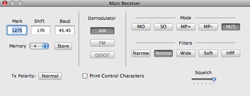
Figure 10 - Dual RTTY Aux
Control Panel
The Print Control Characters is
an option to print received control characters such as
LTRS, FIGS, carriage return and linefeed characters. If
selected, LTRS characters are printed as ltrs in
between angle brackets, FIGS as figs in between
angle brackets, carriage returns as cr in between
angle brackets and linefeeds as lf in between
angle brackets.
Dual RTTY Transmitter
Like the basic RTTY interface, the transmitter section of
the Dual RTTY interface has a text view that your keyboard
entries are made through. The transmit and flush buttons
are on the right of the text view, together with a
indicator that turns red when you are transmitting.
To the left of the text view is a pair of buttons that
controls which tone pair we transmit with. Earlier, we have
stated that the Main and Sub receivers can have its own
tone pair. The Tx (Main, Sub) buttons allow you to choose
to use the main receiver’s tone pair or the Sub
receiver’s tone pair, in case they have different
tone pair offsets.
Depending on whether you have chosen to transmit using the
Main or the Sub receiver's tone pair, the
two receive sections (including the crossed ellipse
indicator) will swap places so that the receiver section
that is closer to the bottom (i.e., the one that is closer
to the transmit interface) will be the interface whose
tones you will be using to transmit with.
Spectrum Display
The top section of the Dual RTTY interface has a spectrum
analyzer that you can select to monitor either the Main or
the Sub receiver as the signal source. The selection is
made using the bottom most popup menu to the right of the
spectrum. You can also choose to turn the spectrum display
completely off (it will save some processor cycles for
slower machines).
Above the receiver selection popup menu is another popup
menu for choosing the dynamic range of the spectrum. There
are three settings, 40 dB, 60 dB and 80 dB. In the 60 dB
position, the spectrum displays a total range of
approximately 60 dB -- each of the green horizontal grid
lines represents a 30 dB change. In a noisy environment,
the 40 dB setting is probably most appropriate. With a very
high dynamic range environment (and if your transceiver and
the A/D converter are capable of better than 60 dB of
dynamic range), the 80 dB position is useful to dig for the
very weak signals.
The top most popup menu controls the integration time of
the spectrum. For tuning around, it is best to use the
shortest (0.2 second) integration time. If you are tuned
and listening to a single station, the longest integration
time (1.5 seconds) provides the most precise tuning aid and
it is also useful for assessing problems with the received
signal such as an overdriven AFSK signal or a FSK
transmitter that has excessive keyclicks.
The spectrum display can be also be switched into a
waterfall display. Notice that the integration time popup
menu has an item called WF. When WF is selected, the
spectrum display will change into a waterfall spectrogram:
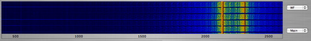
Tuning the transceiver using a
waterfall can be very slow, but it can also provide very
precise tuning for signals that are so weak that neither
the crossed ellipse nor the spectrum plot are practical as
tuning indicators.
Cautionary Note
There is only one transmitted signal from the Dual RTTY
interface. cocoaModem uses the left stereo channel to
output its AFSK signal. If you are using one of the Dual
RTTY receivers to monitor a DX station while using the
second receiver to scan for the QSX, make sure you have set
the proper split on the transceiver when the transceiver is
keyed to transmit. For example, if the physical Main
receiver is watching the DX and you are searching for his
QSX using the Sub receiver of the transceiver, make sure
that you set the transceiver so that the transmitted
frequency is set by the Sub receiver’s VFO of the
transceiver. cocoaModem has no control over which
transceiver VFO it is transmitting through, your
transceiver setting determines that.
Example of Split RTTY
Operation
My stereo sound device is connected to my FT-1000MP's rear
panel stereo jack through a stereo cable. The FT-1000MP
passes its main receiver output to the left stereo channel
and its sub receiver to the right stereo channel in the
rear panel jack. I configure the left channel of the sound
device as my Dual RTTY receiver's Main input device, and I
configure the right channel of the same audio device as my
Dual RTTY receiver's Sub input device.
I then set the FT-1000MP into split operation to activate
both the main and sub receivers with the main
receiver’s IF bandwidth set to 250 Hz and the sub
receiver’s IF bandwidth set to 2.4 kHz.
Next, I tell the FT-1000MP to choose the sub VFO to
transmit through (i.e., split). I then tell cocoaModem to
transmit using the Sub receiver's tone pair.
I tune for the DX using the main VFO knob, initially
setting the Dual RTTY spectrum to watch the Main receiver
to properly tune the DX in. I then set the Dual RTTY
spectrum to watch the Sub receiver and use the
FT-1000MP’s sub receiver knob to tune for the the
QSX, or to find a quiet spot in the spectrum to call.
When I transmit, it will be at where the
transceiver’s sub VFO is set to, thus presumably the
QSX of the DX station.
Using the Dual RTTY Interface
for regular RTTY Operation
The Dual RTTY interface is useful even if you are not using
two separate receivers. Used this way, the Dual RTTY
interface has an advantage over the basic RTTY interface in
that you will have an additional spectrum analyzer or
waterfall display as an additional tuning aid. This is
especially useful if you are using a wide IF filter.
To use the Dual RTTY interface as a single receiver, simply disable the Dual RTTY’s Sub receiver in its configuration panel (set the state to inactive) , and select the Main receiver as the source for the spectrum display. Then, use the Main Receiver as you have been using the regular RTTY Mode.