
cocoaModem PSK Interface
Kok Chen, W7AY
[w7ay (at) arrl
(dot) net]
Last updated: July 1, 2006
Index (User's Manual - PSK Interface)
General Information
Aural Monitor
Accessibility (Incremental Speak and Voice Assist)
Macros
RTTY Interfaces
PSK Interface
-
Config Panel
- PSK Control Panel
-
Operating PSK31
-
Raw Output
- Dual Transceiver
-
Table View
- Turning a Transceiver Off
-
PSK Transmission
Hellschreiber Interface
CW Interface
ASCII Interface
SITOR-B Receiver
HF-FAX Receiver
Synchronous AM Receiver
Versions
Part II
PSK Interface
cocoaModem's PSK Interface allows you to receive two different stations that appear as audio PSK tones within a 2.2 kHz passband, and to generate one transmitted signal. The two receivers are independent and can be independently set to decode either BPSK31, QPSK31, BPSK63, QPSK63, BPSK125 or QPSK125 signals.
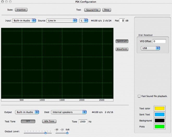
Config Panel
The PSK Config Panel is shown below in Fig 1. After selecting the PSK Interface in the main cocoaModem window, you can open the Config panel by selecting Config under the Window menu in the Menu bar. You can also open the Config panel by using the Command-Option-comma keyboard shortcut.
Most of the components of the
Config Panel are already described in the General Information section of the
manual. PSK specific interfaces are described here.
VFO Offset
On the right of the PSK Configuration panel is a Dial
Readout box. This box determines how the frequency scale of
the waterfall in the main PSK Interface
window is labeled. The default contents of this box is a
frequency offset of zero with the popup menu set to
upper side band. This would be the setting you should
use when operating PSK using a regular SSB transceiver
in USB mode, as if you are transmitting voice.
You can leave the Dial Readout box alone, and cocoaModem
would work fine even if you are not using USB voice mode.
However, if you are using some other mode than USB voice
mode with cocoaModem, you might want to take a little time
now to set the PSK Config parameters to the sideband and
VFO offset of your transceiver, cocoaModem provides a very
simple way to figure out where a PSK signal is on the
spectrum, whether you are using USB or LSB and whether
there is a VFO dial offset on your transceiver.
When left in the default state (VFO offset set to zero, and
USB selected), the frequency scale that appears below the
cocoaModem PSK waterfall shows the actual audio frequency
of the audio PSK tone. If the audio PSK signal is applied
to an upper sideband transmitter, you will be emitting a
PSK signal that is the same amount away and higher from the
suppressed carrier frequency. The suppressed carrier
frequency is what usually shows on the VFO dial of the SSB
transceiver.
I.e., if the transceiver is using USB and the dial shows a
suppressed carrier frequency of 14071.0 kHz, then a 1.5 kHz
PSK tone will be transmitting a signal precisely at 14071.0
kHz + 1.5 kHz, or 14072.5 kHz.
On the other hand, if your transceiver is operating in LSB,
the same 1.5 kHz audio tone will cause the actual transmit
carrier to be located at 14071 kHz - 1.5 kHz or 14069.5
kHz.
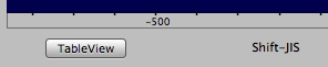
To account for this difference, just select LSB in
the popup menu if you are operating in LSB. When you do
this, you will see that the 1.5 kHz tone now appears above
a scale that reads negative 1500.
Many rigs can also apply a VFO dial offset when used in
AFSK mode. The reason for the VFO offset is so that the
dial reads the Mark frequency of an RTTY signal, rather
than the meaningless suppressed carrier frequency when
operating in digital modes.
Check with your transceiver's manual what VFO offset is.
If you are using a non-zero VFO offset, you will notice
that the scale that is under the waterfall consists of both
positive and negative numbers. To identify the precise
frequency a PSK signal is on the waterfall, simply add the
number to the transceiver’s VFO dial reading (or
subtract the number from, if it is a negative number). The
result should be the actual frequency you will be
transmitting at.
You can very simply test to see if you have entered the
correct number into the dial readout box by tuning your
transceiver to precisely 10.000 MHz with the transceiver in
the same mode that you operate PSK in. If your
transceiver's local oscillator is accurate, you should hear
WWV’s carrier as a line on the waterfall precisely
above the 0 Hz marker.
When you select LSB mode in the popup menu, cocoaModem also
flips the waterfall so that the higher frequency on the RF
spectrum is always towards the right.
PSK Test Tones
cocoaModem provides a PSK test signal for setting a proper
audio output level from the computer, as shown in Figure 2
below.
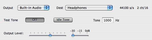
To familiarize yourself with
the test signal, you can initially set the output device to
use the Built-in speakers of the Macintosh. You will be
able to hear what the output controls do.
The test tone is enabled when you press the Idle
Tone button. The audio frequency of the tone can be
set in the Tone field.
If you had selected the Built-in speakers with the output
device menu, you should be able to hear the familiar PSK31
sound on the Macintosh’s speakers when you depress
the Idle Tone button.
You should also be able to adjust the sound volume using
the output level and output attenuation sliders.
Once you are familiar with the output controls, you are
ready to hook up your output sound device to the
transceiver and follow the transceiver’s AFSK level
adjustment procedure.
Use one of cocoaModem’s test tones when the
transceiver manual calls for a test signal. Adjust
cocoaModem’s output levels and any external devices
(such as the trim pot in a SignaLink SL+ interface) to
satisfy the transceiver’s requirements. The main
purpose of the AFSK adjustments is to make sure that you
are operating within the linear region of an SSB
transmitter. Usually, that means that the audio levels have
to be reduced to the point where there is no ALC activity
in an SSB transmitter. It is extremely important that you
do this, otherwise your signal will be so wide that no one
else can operate near to your transmit frequency.
Typically, the procedure is to increase the the audio drive
until you notice ALC kicking in, and then back off from
that position so there is again no ALC action. Your
transceiver manual should cover this under the AFSK or
Packet description.
The output slider in the PSK configuration panel adjusts
the gain on the D/A converter itself, whereas the stepped
attenuator reduces the numerical amplitude of signal that
is generated by cocoaModem. If you have a choice of various
combinations (trim pots, sliders, etc.) try to keep the
“attenuation” level to the minimum (0 dB) as
long as you can use other means to reduce the audio level
to the transceiver. You will generate the cleanest
transmitted signal that way.
cocoaModem has a built-in time-out for the PSK test tone.
This keeps you from accidentally leaving the transmitter on
while you are making adjustments to the audio levels.
cocoaModem will turn off a test tone if it has been on
unattended for more than 3 minutes. If you need longer than
3 minutes to adjust the audio levels, you will need to
press a test tone button again. It is fine to press a test
tone button while the tone is being played. It will extend
the timeout by 3 minutes when you do this.
Leaving the PSK Configuration panel will also terminate the
test tone.
PSK Interface
Figure 3 shows cocoaModem's PSK Interface.
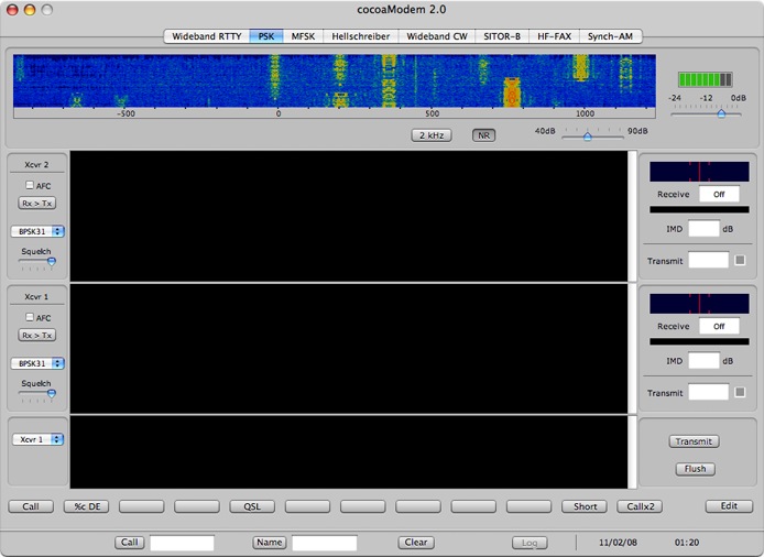
The PSK Interface is loosely
separated into six groups. Just below the tabs is the main
PSK Control panel with the waterfall display, below that
are two PSK Receiver sections, followed by the PSK
Transmitter section, then followed by the row of macro
buttons and finally the QSO Info bar.
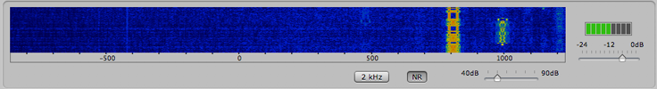
PSK Control Panel
Figure 4 shows the PSK Control Panel. It consists of a
waterfall display, a dynamic range control for the
waterfall, input level control and signal level indicator.
The input level control and the
signal level indicator are already discussed in the
General Information section of the
manual.
The Waterfall spectrogram occupies most of the space of the
PSK Control Panel. Notice that the water
“falls” upwards in cocoaModem's spectrograms. I
have chosen this direction so that the most recent spectrum
line is closest to the frequency scale at the bottom of the
display. The alternative would be to place the labels at
the top of the waterfall, which is not as visually pleasing
to me.
Notice the button that has the caption 2 kHz. In the 2 kHz
position, the waterfall display shows updated spectra in
the audio range from 400 Hz to 2400 Hz. The strength of a
signal is displayed both as an intensity change and color
change. Weaker signals are darker, and stronger signals are
brighter. Weak signals start as a deep blue, then
transitions to cyan, followed by yellow and finally red.
When "depressed," the waterfall width button switches to 4
kHz, showing a waterfall from about 400 Hz to about 4400
Hz. Please note that many transceivers are limited to
working in a 2.4 kHz bandwidth.
The scale beneath the waterfall shows the offset frequency
of the signal from the transceiver’s VFO dial if the
sideband and VFO offset have previously been set in
the Config Panel.
The dynamic range of the waterfall display is controlled by
a slider to the right and below the waterfall display
itself. The control allows you too select the dynamic range
of signals in the waterfall and can bet set in 10 dB steps
from 40 dB DR to 70 dB DR.
With the slider at the 70dB position, the darkest part of
the display (deep blue) is about 70 dB below full scale
(bright yellow/red regions). In the 40 dB position, any
signal that is 40dB below the peak level will be dark and
only very strong signals will show up as yellow. Placing
the slider at 70 dB will show more of the weak signals, but
it will also show more noise.
When the band is very noisy it is often easier to spot the
stronger signals if you set the control for a lower dynamic
range. When the band is quieter, you can find the weaker
signals by displaying a larger dynamic range on the
waterfall. The place where the display looks the most
useful depends on propagation conditions, how noisy your
location is, the directivity and gain of your antenna, etc.
Operating PSK31
Some of the interfaces that are common to other modes are
discussed in the General Information section.
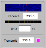
PSK Reception
Below the waterfall are two independent and identical PSK31
“transceivers.” Each transceiver is arranged
with some controls at the left, the text view for the
receiver in the middle and the frequency and phase displays
on the right. Figure 5 shows a detailed view of one of the
transceivers while in the middle of decoding a PSK31
signal.
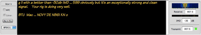
Starting with the control
section on the left of Fig. 5, you will see the name of the
Transceiver. Below it is an AFC button and below it is a
button to select between coherent and non-coherent
demodulation (the current implementation only supports
coherent demodulation – but I would like to
experiment in the future with non-coherent demodulation to
see if any disadvantage is actually noticeable on HF).
Below that is a button (Rx>Tx) to manually sync the
transmit frequency to the receive frequency.
Below the transmit/receive sync button is a menu to select
the PSK interface, this menu is defaulted to BPSK31.
BPSK31, BPSK63, BPSK125, QPSK31, QPSK63 and QPSK125 are
selectable from this menu. BPSK31 (Binary PSK31) is the
most common of all amateur HF PSK modes.
Raw Output
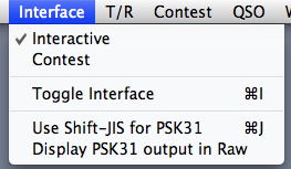
For debugging and other purposes, the output can be set to
display raw hex code by selecting the Display PSK31
output in Raw item in the Interface menu of the main
menu bar.
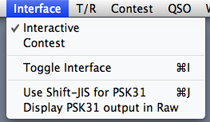
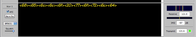
In the raw mode, the hex bytes are displayed between angle
brackets, as shown below.
- AFC
A few words need to be made here about automatic frequency
control (AFC) and the philosophy of the scheme I have
implemented in cocoaModem. This could be very different
from what you are used to with other PSK31 programs, and it
is worth understanding what is happening inside cocoaModem.
cocoaModem uses three separate frequency control
“loops.” These are the acquisition loop, a
frequency tracking loop and a phase tracking loop.
When a new frequency is selected by clicking on the
waterfall, cocoaModem’s PSK receiver initiates an
acquisition phase. Unless the signal is very noisy,
distorted (lots of IM distortion) or there are substantial
amounts of adjacent channel interference, you can click
quite far away from the center of the signal and the
receiver will still be able to successfully lock in.
The acquisition phase is executed whether or not the AFC
button in the receiver control panel is set. Its purpose is
to allow you to click only approximately on the waterfall.
cocoaModem’s acquisition loop has no other purpose in
life.
Once the frequency is locked to within a fraction of a
cycle per second, the PSK31 receiver terminates the
acquisition phase. If the received signal makes a large
abrupt change in frequency after this point, cocoaModem
will not move towards it.
After leaving the acquisition loop, the PSK31 receiver now
turns on the frequency tracking loop if the AFC button is
on. This allows the receiver to track a slowly drifting
PSK31 signal. Most modern transceivers have quartz based
synthesizers and do not drift to any appreciable degree
after a minute or two of warm up time. For this reason, the
AFC button in cocoaModem is defaulted to off. You can turn
the AFC tracking loop on manually if you feel that the
received PSK31 signal is drifting. However, with modern
equipment, if the acquisition loop has done its job
properly, you will not need to use the frequency tracking
loop.
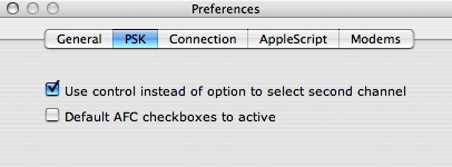
You can default the AFC buttons to always be active when
you launch cocoaModem by setting the appropriate checkbox
in the PSK preferences shown in Figure 6 below. You can
open the Preference panel from the cocoaModem menu in the
Menu Bar.
If the frequency remains within
a fraction of a cycle to the reference, cocoaModem turns on
the phase correction logic. cocoaModem does not really
apply a phase correction term to the internal local
oscillators, but simply measures the phase errors and then
applies the deviation from an ideal phase to the
demodulator itself.
cocoaModem also does not implement a tracking "net" button.
When pressed, the sync (Rx > Tx) button momentarily
transfers the current PSK31 receiver’s frequency to
cocoaModem’s PSK31 generator (transmitter). There is
no further tracking.
- Selecting PSK31 Frequency, the PSK
Frequency Indicator and Phase Indicators
The easiest way to “tune” the PSK31 transceiver
is to mouse click on the waterfall.
A green line appears at the cursor location and this
frequency is immediately transferred to the Receive
Frequency field at the right of the Xcvr 1 section
(Figure 5). The Frequency Indicator above
the receive frequency text field should also start to
show an expanded version of the waterfall around the
region that you have clicked. The longer red line at the
middle of the frequency indicator is the center of the
PSK31 receiver’s passband. The shorter tick marks
are 16.125 Hz away from the center. These two shorter
tick marks show the locations of the sidebands of an
idle PSK31 signal.
If the initial click is far away from the center of the
signal, you can watch the acquisition loop
“pull” the signal in on the frequency
indicator. While the receiver is acquiring the signal, you
can also see the numerical value in the receive frequency
field change – this shows that the local oscillator
in the PSK31 receiver is trying to match itself to the
center of the PSK signal. The green line in the large
waterfall also tracks this movement.
When the frequency acquisition succeeds, the frequency in
the receive field is transferred to the Transmit Frequency
text field. This fixes the frequency you will be
transmitting on unless you later click on the sync (Rx >
Tx) button to transfer a later receive frequency into the
transmit frequency field. You can also directly type in a
different frequency into the transmit field. After this
initial setting of the transmit frequency, the transmit
frequency will no longer track the receive frequency,
whether or not the AFC button is on.
You can also type a frequency directly into the receive
frequency field. If you do this, the receive frequency will
switch immediately to the frequency you have entered and
cocoaModem will not enter the acquisition loop, nor will
the frequency be transferred to the transmit frequency
field (use the sync button if you want to lock the
transmitter to this new receive frequency).
Once the acquisition phase has locked on to a signal, you
should see the Phase Indicator settle down to a single
stable line if the signal is clean and strong. This line
need not be perfectly centered to get a good print. A noisy
signal will cause the yellow line to jump around. The copy
will not be solid if the yellow phase line jumps around a
lot.
A severely distorted signal could cause some ghost lines to
appear. You should also see printing degrade when this
happens.
If you see three stable yellow lines, usually a strong line
at the center and two other weak lines near the left and
right edges of the phase indicator, it is most likely that
the station is transmitting in QPSK31.
QPSK31 uses quadrature phasors at the same baud rate as
(hence twice the bit rate of) BPSK31. A rate one-half
convolution code provides error correction and drops the
information rate back to the 31.25 bits per second of
BPSK31. At moderate and good signal to noise conditions,
QPSK31 can provide a cleaner copy than BPSK31. However,
poor signal to noise conditions copy will be better with
BPSK31 (which explains the relative popularity of BPSK31
over QPSK31).
Immediately to the right of the Transmit Frequency field is
a small transmit indicator that shows the state of the
transmitter section of this transceiver. This indicator can
be any one of four possible colors. If this transceiver is
not selected by the transmit control, the transmit indicator
will be gray. Unless both the receive frequency and the
transmit frequency have been chosen, the color of the
indicator will also be gray. In essence, when the
indicator of a transceiver is gray, you will not be able
to transmit through that transceiver.
If this transceiver has been selected by the transmit
control, and both the receive frequency and the transmit
frequency have been chosen, the transmit indicator of the
transceiver with turn green, indicating that the
transceiver is ready for transmission.
While a transmission is in progress, the indicator will
show red. While the mode of the transceiver is in the
process of changing from transmit to receive, the indicator
will turn yellow while waiting for remaining text to be
transmitted. Once the transceiver is idle, the color of the
indicator will again turn green.
- Fine Tuning (RIT)
You can manually fine tune the receive frequency by holding
down the command key and typing on the arrow buttons on
your keyboard. The up and down arrows moves the receive
frequency by one Hertz at a time and the left and right
arrows moves the frequency by a tenth of a Hertz at a time.
This is a good way to center the yellow phase indicator if
you have the AFC turned off. A perfectly centered phase
indicator can provide a slightly better print when copying
marginal signals.
Note that the fine tuning described here has no effect on
the transmit frequency. You can therefore treat the arrow
keys the same way as you use the receive incremental tuning
(RIT) function found on transceivers.
If you want to re-synchronize the transmit frequency to the
receive frequency, simply use the Rx>Tx button in the
control section at the left of the transceiver’s text
view.
To fine tune the receiver of the second transceiver, hold
down both the Command and Option keys (or the Command and
Control keys, if your PSK preference shows that you prefer
to use the control key to select the alternate channel).
Because some desktop managers "traps" the Command-click
keys for their own use, cocoaModem provides an option for
you o choose whether to use Command-click or Option click
to control the RIT. The preference checkbox is in the PSK
Preferences that was shown earlier in Figure 6.
Fine Tuning with a Scroll Wheel
Mouse
If your mouse comes with a scroll wheel, you can also use
it to fine tune the PSK receiver.
To do this, the cocoaModem window has to be the active
window. Clicking anywhere on the brushed metal part of
cocoaModem's brushed metal window (or clicking on the
window’s title bar if you chose not to use the brush
metal window) will make cocoaModem’s window active if
it is not already active.
Move your mouse into the waterfall area. Do not click the
mouse, since that would select a new frequency to use. The
scroll wheel of the mouse should now tune the RIT. Holding
down the Option key (or the Control key if that is in your
PSK preference) when using the scroll wheel to apply RIT to
the second transceiver.
- Intermodulation Distortion (IMD)
Measurement
The field that shows the IMD of the received signal is
below the Phase Indicator.
This is an estimate of the
intermodulation distortion product of the received signal,
measured while the PSK signal is sending the idle pattern.
A clean PSK31 idle signal appears as two pure sine wave
carriers that are 31.25 Hz apart (each 16.125 Hz from the
center frequency) – this is the familiar two-tone
signal that shows up on the waterfall as a pair of lines
when the other end is transmitting but not typing anything.
In addition to the pair of lines, intermodulation
distortion will cause other spectral products (lines that
are further away from the center) to appear in the
waterfall. cocoaModem compares the strength of the spectral
components around 48 Hz from the center frequency with the
strength of the signals around 16 Hz from the center
frequency and reports the ratio in the IMD field. I.e.,
cocoaModem measures and reports the third-order IMD.
cocoaModem is moderately conservative when it comes to
reporting an IMD number and prefers to not output an IMD
measurement when it thinks that it cannot make an accurate
assessment of the IMD.
If the signal appears to be noise limited (the estimated
amount of noise is larger than the distortion products),
cocoaModem will report a NL in the IMD field rather than a
number (which is bound to be wrong anyway when the
measurement is noise limited).
cocoaModem also does not make an IMD estimate when a signal
is not tuned to within about 3 Hz of center. When a signal
is perfectly tuned in, the yellow line in the phase
indicator will be perfectly centered. You can see how much
3 Hz is by observing how much this line moves when a 3 Hz
offset (three up or down arrows on the keyboard) is applied
to the RIT.
A few words of advice are in order here.
With a weak station (a signal that does not appear as
bright yellow against a relatively clean blue background),
don’t even bother with sending an IMD report; it
would not reflect the true IMD of the signal. It is better
to report to the station that you are working that their
signal is too weak to make an IMD measurement, rather than
to give him a wrong report. Even with a strong station, you
may still need to ask them to send a long idle (a second or
two) before IMD readings can be measured.
With a strong station, please be aware that your own
receiver's front end could be contributing to a poor IMD
reading. With typical receivers, you will need to
apply enough RF attenuation until the signal falls below
the S5 mark on the S-meter before a meaningful measurement
should be taken.
You can experiment with what an acceptable signal strength
is for your own receiver. Tune in a clean strong PSK31
station that is showing better than -25 dB IMD. Start
applying RF attenuation on your transceiver and you should
see the IMD figure improve (i.e. larger negative number),
keep on applying RF attenuation until the IMD number no
longer improves. The strength of the signal on the S-meter
indicates the approximate signal level you should use for
making future IMD readings.
If you don’t bother to take these steps, it is best
not to report an IMD number at all since it would
invariably be wrong (and the reason why the IMD reports you
see on the air for the same station are all over the map.
- Click Buffer
The normal way to tune in a station is to click on the
signal in the waterfall. This should also set up the proper
frequency in the transmit frequency field for subsequently
working the station.
Once the Phase Indication “snaps” in to the
signal, you should see print in the receive text view in
the middle of the receiver section.
With v0.13, cocoaModem 2.0 introduced the concept of a
click buffer. The click buffer is a temporary
audio buffer memory that is created when a signal is first
clicked on the waterfall, the full audio bandwidth signal
is recorded into this buffer while the PSK decoder is
trying to acquire lock on the incoming signal. Once phase
lock is achieved, the buffer is played back, but at a
higher than real-time speed, until the buffer catches up
with the incoming audio stream. If the signal has not
drifted in phase, cocoaModem will print the signal from the
instant that you clicked on the signal instead of waiting
until phase lock is achieved before its starts to decode
and print the incoming audio stream.
Starting with v0.27 of cocoaModem, the click buffer concept
has been extended.
The PSK interfaces now maintains a constant 20 seconds
(approx.) worth of audio buffering. When audio samples are
received from the sound device, they are copied into this
ring buffer (which behaves like a "tape loop" on old
fashioned tape recorders). At any point in time, there is
always 20 seconds of "history" that is buffered.
When the waterfall is clicked, the horizontal position of
the click is translated into a frequency offset to use for
filtering and demodulation. The vertical position of the
click is captured as a time parameter. This parameter is
then translated into a position in the audio ring buffer.
Instead of feeding the current input audio samples to the
demodulator, the audio samples from the buffer is played
back at up to eight times normal speed until it finally
catches up with real time data.
If you click at the bottom part of the waterfall, you will
start demodulating the most recently received stream. If
you click towards the top of the waterfall, as long as you
have not moved the VFO dial on your radio in the meantime,
you will be demodulating a signal that first appeared about
20 seconds ago. If you click halfway up the waterfall, the
demodulating will start from about 10 seconds ago.
In effect, what results is a true WYSIWYG waterfall
clicking. Demodulation will start from the place that you
have clicked in the waterfall even if the signal has
stopped transmitting by the time you'd clicked on the
waterfall trace.
Dual Transceiver
Notice that the PSK window shows two transceiver sections,
one labeled Xcvr 1 and the other Xcvr 2. cocoaModem
supports two independent receivers that behave in identical
manner.
When you click on the main waterfall, the operating
frequency is transferred to Xcvr 1 and the location of the
selection is indicated by a green line in the main
waterfall.
If you hold down the Option key of the keyboard when you
click on the waterfall, the selected frequency will be
transferred to Xcvr 2 instead of Xcvr 1, and this selection
will show up on the main waterfall as a magenta line.
Fine tuning also works on the second
receiver by clicking on the arrow keys on the keyboard
while you hold down the option key in addition to the
command key.
Instead of using the Option key to select Xcvr 2, you can
instead choose to use the Control key. To do this, go to
the Preference panel (Command-semicolon keyboard shortcut)
and select the PSK tab and click on the checkbox (see
Figure 6).
One advantage of using control clicks instead of option
licks is that you can now use the right mouse button to
select and deselect the second PSK receiver.
There is a caveat if you happen to use an application
called Desktop Manager to create virtual desktops in MacOS
X. Desktop Manager traps the control-left arrow and
control-right arrow keys. If you choose to use the control
key to select Xcvr 2, and you are also using Desktop
Manager, you can no long apply fine RIT (0.1 Hz increments)
to the second PSK receiver since cocoaModem cannot receive
those particular keystrokes from the operating system. You
can still use the rough RIT (1 Hz increments) since those
are accessed through the up and down arrow keys instead of
left and right arrow keys. You can also still use the
scroll wheel of a mouse to fine tune. This is not a factor
if you don’t use Desktop Manager.
The rest of the behavior of Xcvr 2 is identical to that
described earlier for Xcvr 1.
Table View
The PSK interface has a receive-only Table View mode. It is
an alternate way to using the waterfall to find and decode
BPSK31 signals. It is useful for automatically scanning the
PSK sub-band to look for stations that are issuing CQ
messages, for casually monitoring the PSK sub-band or for
quickly finding the QSX of a DX station within a pileup.
In the Table View mode, the PSK interface simultaneously
displays the decoded text from up to 21 demodulators.
Because of that, it is not recommended for use with older
G3 based computers or slower G4 based computers.
The decoded text from the demodulators that have captured a
signal appear in separate rows of a table view. To enable
the Table View mode and display its window, click on the
TableView button that is below the waterfall.
Disable the table view demodulators by closing the window.
When enabled, you should see a
window that has a table view and some controls at the
bottom, as seen below. By dragging the bottom right hand
corner of the window, the window's height and width can be
adjusted to match your needs. At the maximum height, the
table shows all 21 demodulators. At the expense of heavier
processor usage, you can also increase the width of the
window.
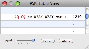
The left hand column of each
row of the table view shows the decoded text, with the
right hand column displaying the tone frequency. This
frequency corresponds to the frequency scale below the PSK
waterfall, and includes any offsets caused by the USB/LSB
selection and selected VFO Offset value. The top of this
table corresponds to the left side of the waterfall.
To reduce processor usage, the demodulators in the
TableView are simpler and are not as sensitive as the
primary demodulators in the PSK interface, and they only
work with stronger BPSK31 signals (no QPSK31 nor PSK63 or
PSK125). The squelch control is global for all the signals
in the TableView.
You can transfer the frequency from the Table View to the
main demodulators in the PSK interface by clicking on an
active row (any row that contains frequency information) of
the table. This will set both the receive and transmit
frequencies in the primary transceiver, allowing you to
transmit to the given frequency without having to click on
the waterfall.
Just as a control- or option-click in the waterfall chooses
Xcvr 2 of the PSK interface, a control- or option-click on
a table view row will transfer the selected frequency to
Xcvr 2 instead of to Xcvr 1 of the PSK interface. (Remember
that you choose whether to use control-clicking or to use
option-clicking by selecting the checkbox in the PSK
section of the cocoaModem Preferences.)
The "Rescan" button in the TableView window lets you
release all rows of the table view and create a new scan of
the signals. If a certain row of the table view has
previously been selected, only the neighborhood of that
frequency is rescanned. (Remember that, in Mac OS X, you
deselect a row of a table view by command-clicking on a
selected row.)
The Alarm button opens a small interface that allows you to
highlight certain strings in the table view.
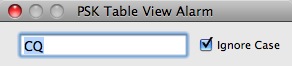
Notice that we had entered a
string "CQ" in this case, and notice that the strings "CQ"
in the table view above are highlighted in red. You can,
for example, enter the call sign of a DXpedition to
identify their signal and the signals of the people who are
working the DXpedition. On slower processors, it is
advisable to keep the alarm field empty.
The PSK TableView can be opened with the Command-B keyboard
shortcut. The PSK TableView shortcuts are in the Interface
menu of the cocoaModem Menu Bar.
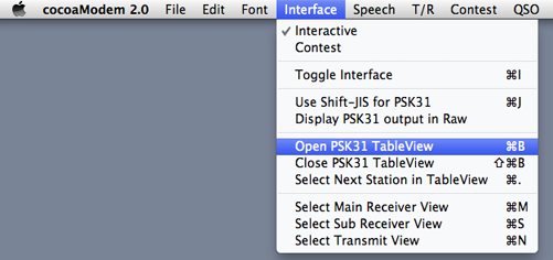
You can also select the next
active table view row (and transferring the selection to
the PSK Interface's main receive waterfall) by using the
Command-period keyboard shortcut. If the tableview is
empty, you will hear two short beeps.
Turning a Transceiver Off
When you click anywhere on the waterfall while the shift
key of the keyboard is held down, Xcvr 1 will turn off.
When you click anywhere on the waterfall with both the
shift and the option (or control key, if you have set that
as your preference) keys held down, Xcvr 2 will turn off.
PSK
Transmission
To work another station that you have been copying, first
check that the transmit frequency is the same as the
receive frequency. If they are not identical, you should
click on the Rx>Tx button to sync the transmit frequency
with the receive frequency before transmitting.
If you are starting a transmission on an empty frequency,
the easiest way to set a transmit frequency is to click on
an unused space in the waterfall. You can then transmit
once the acquisition loop has settled down and cocoaModem
has synced the transmit frequency to the receive frequency.
In this latter case, the actual frequency may have moved a
little from the spot you first clicked on, since the
acquisition loop may have adjusted the local oscillator
frequency due to a bias in the received noise. If you wish,
you can use the arrow keys to fine tune the receive
frequency, then syncing the transmit frequency to it using
the Rx>Tx button.
Another way to set the frequency is to directly type the
frequency you want to use into the receive frequency field,
then click on the sync button to make the transmit and
receive frequency fields agree with each other, and finally
check where the green line (or magenta line if you are
using Xcvr 2) in the main waterfall is, to make sure you
are not falling on top of a frequency that is in use.
(Remember to also QRL the frequency, please.)
Figure 7 shows the transmitter section of the PSK
interface.

Figure 7 -
PSK Transmitter Section
- PSK Transceiver
Selection
You can choose to transmit at the frequency selected by
Xcvr 1 or the frequency selected by Xcvr 2 by selecting one
of them from the popup menu in the transmit control on the
left of the transmit text view (Figure 7 above).
When you choose to transmit with the frequency that is
selected by Xcvr 1, the Xcvr 1 user interface (seen in
Figure 5 above) will be shown positioned just above the
transmit interface, as seen in Figure 3.
When you switch to Xcvr 2, the two transceiver sections
will swap places in the window in Figure 3 (this behavior is new
with cocoaModem 2.0 v0.33), i.e, Xcvr 2 will be
positioned directly above the transmit section and Xcvr 1
will move to the position above Xcvr 2.
This allows you to better identify which station you are
working -- the station that you are working will always
be displayed in the transceiver that is closer to the
transmit interface. You can identify the frequency you
will be transmitting at by looking at the color of the
small indicator next to the transmit frequency field of the
transceiver's control panel. The color in that indicator
will correspond to the color of the frequency marker in the
waterfall. Shown below is the color of the indicator when
Xcvr 2 is selected. If Xcvr 1 is selected, the color of the
indicator would be green.
- Transmit Buffer
When text is inserted into the transmit text view in the
PSK interface, either from the keyboard or from macros, it
enters a transmit buffer and stays there until every
character is transmitted. If the PSK modem is not in the
transmit state, the characters simply stay in the buffer
until the next time the transmit state goes active (or
until the buffer is flushed). As each character in the
transmit buffer in the state of being transmitted, the
character is echoed to the receive text view. The color of
the echoed text can be chosen to be different from the
color of the other texts in the PSK interface.
Notice that the font in the transmit view can also be
changed using the same procedure explained earlier.
- Transmitting Text
To start sending the contents of the transmit buffer, press
the Transmit button that is on the right of the
transmit text view.
When the Transmit button is pressed, the button caption
changes to Receive and the color of the transmit indicator
of the target transceiver should turn to red, indicating
that you are now transmitting. Clicking on this button
again will return you to the receive mode.
Whenever you are in transmit mode (the red indicator is on)
and the transmit buffer is empty, cocoaModem will insert an
idle character into the character stream.
When characters are entered into the transmit scroll view,
the new characters be transmitted instead of the idle
characters. Characters can be typed directly into the
transmit view, or they can be entered through the use of
macros.
Any text that is typed ahead that has not yet echoed to the
receive view can be cancelled by using the Flush
button that is beneath the Transmit button. Errors in PSK31
can be corrected by using the delete key on your
keyboard. This is encoded into the Varicode backspace
character and is transmitted over the air to erase a
character at the receiving end.
- Flushing the Transmit
Buffer
Notice the Flush button that is below the
Transmit button. The purpose of this button is for
clearing all characters in the transmit buffer which have
not yet gone out on the air. The Flush button does not end
the transmission. If you are in transmit mode, cocoaModem
will resume sending idle characters. If you’re typing
ahead in receive mode, cocoaModem simply wipes the entire
transmit buffer clean. This includes any text macros you
have inserted into the transmit buffer.
- Exiting the Transmit
Mode
To return to receive mode, press the Receive
button (the Receive is at the same location as the Transmit
button).
If there is still text in the transmit buffer when
returning to receive mode, the red transmit indicator in
the PSK transceiver will turn yellow while the rest of the
characters in the transmit buffer is being transmitted and
the indicator remains yellow until the transmit buffer is
emptied. When the transmit indicator finally turns green
again, cocoaModem has returned to receive mode. You can
also use the keyboard shortcuts that were described in
General Information to switch between
receive and transmit modes.
Operating PSK63 and
PSK125
Select BPSK63, BPSK125, QPSK63 or QPSK125 in the PSK mode
popup menu in the xcvr1 or the xcvr2 control panel to place
the PSK transceiver into the fast PSK modes. Each
transceiver can be independently set to its own mode.
KH6TY introduced the use of BPSK63 and QPSK63, which are
the double rate versions of BPSK31 and QPSK31. Instead of a
symbol rate of 31.25 baud, the symbol rate of PSK63 is 62.5
baud (the nomenclature “BPSK63” refers to the
62.5 rate that has been rounded up to 63).
PSK63 uses twice the bandwidth of PSK31 and can be
identified on the waterfall as such. When an idle tone is
transmitted in PSK63, the spacing between the two lines in
the waterfall is about 62 Hz wide, compare to the 31 Hz
width of PSK31.
PSK63 provides twice the throughput as PSK31. However,
PSK63 also requires about twice the amount of transmitted
power to maintain the same error rate as PSK31, and as
mentioned above, it also uses up twice the amount of
spectrum space.
Except for a change in transmission speed and a wider
spectrum, operating in PSK63 with cocoaModem is no
different from operating in PSK31.
Similarly, PSK125 is a quadruple rate PSK31 mode. While
PSK125 has 4 times the throughput of PSK31, it requires 4
times the power of PSK31 to maintain the same character
error rate. It also take up 4 times the bandwidth of a
PSK31 signal.
Japanese Reception and
Transmission
cocoaModem follows the ad-hoc standard for transmission and
reception that is used by Japanese PSK31 programs.
Characters are represented by the Shift-JIS (JIS X 0208) encoding and
encompasses Hiragana, Katakana and Kanji characters. The
16-bit Shift-JIS encoding is first separated into two
8-bit bytes. The two bytes are then encoded into PSK31
differential phase shift modulation using the standard
8-bit PSK31 Varicode that is used for transmission of
extended ASCII (e.g., European alphabets). The most
significant byte is transmitted first.
Since the most significant byte of Shift-JIS is a subset of
all possible 256 values, cocoaModem uses that information
to help determine which is the "upper byte" of Shift-JIS
when a stream of 8 bit Varicode encodings is received.
During transmission, cocoaModem provides an additional step
of converting from the Unicode that is used in Mac OS X into
Shift-JIS,. There is the addition step of converting
from Shift-JIS to Unicode during reception.
Please be aware that Japanese transmission is quite slow.
Since each character contains two extended Varicode (each
of the extended Varicode has 12 data bits and two stop
bits) the character error rate is also much higher than the
use of lower case ASCII characters, which has on average
approximately 7 bits per character.
To receive and transmit double-byte Shift-JIS encoding,
select the Use Shift-JIS for PSK menu item in the
Interface menu of the main Menu Bar, or use the Command-J
keyboard shortcut.
When Shift-JIS is selected, a "Shift-JIS" caption will
appear below the PSK31 waterfall display:
For sending, use the standard Japanese input techniques on Mac OS
X; for example, using the Kotoeri method or using the
Japanese Kana palette in Mac OS X.
Next (Hellschreiber)