Basic RTTY Interface
Please note that the Basic RTTY Interface is deprecated. It is kept around but no new functions will be added directly to it. As new demodulators are developed, the Basic RTTY Interface may not be able to use them. Please use the Wideband RTTY Interface instead.
The basic RTTY Interface shown in Figure 3 is loosely separated into five sections. Just below the tabs for selecting cocoaModem interfaces is the RTTY Control Panel, below that is the Receive text view, followed by the Transmit text view, then the row of macro buttons and finally the QSO Info bar.
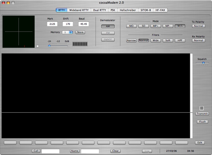
Figure 3 - Basic RTTY
Interface
RTTY Control
Panel
The RTTY Control Panel (Figure 4) contains the control and
display functions that are found in a typical HF Modem.
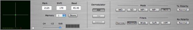
On the left of the control
panel is the crossed ellipse tuning indicator. To the right
of that are the tone pair control and the input attenuator
and a VU meter.
Currently, cocoaModem only supports an AM demodulator in
the form for a matched filter, the button for the other
modulators are grayed out.
The mode buttons allow you to select Mark-only (MO),
Space-only (SO), strong Multipath (MP+), weak Multipath
(MP-) and Mark-space (M/S) demodulation. Mark-space is the
demodulation mode that should work best in almost all
cases. Sometimes, it is possible to copy using Mark-only if
there is an interfering signal covering up the Space tone,
or to copy using Space-only when there is an interfering
signal covering up the Mark tone. Similarly when there is
multipath present, copy can sometimes be improved using the
Multipath modes.
The “normal” filter is the optimal filter to
use under normal circumstances (an RTTY signal with band
noise but no interfering signal close by). When there is a
nearby interfering signal, the narrow filter might provide
better copy. Likewise, a weak signal but clear of any
interference might give slightly better copy using a wider
filter.
Finally, there are two polarity buttons on the far right of
the control panel whose use is described in the section of
the manual describing RTTY tone pairs.
Operating RTTY
After configuring the interface (see main RTTY documentation), you are ready for RTTY
operations. Be sure to remember to turn on the Active
button in the Config panel.
RTTY is transmitted over the air as a Frequency Shift Keyed
(FSK) signal. A "0" bit is transmitted as one of the two
FSK carrier frequencies (called the space frequency)
and a "1" is transmitted as the other carrier frequency
(called the mark frequency).
When you send a character in RTTY, you will be switching
between 1's and 0's, and the FSK signal will shift between
these two frequencies and generate corresponding sidebands.
On the spectrum, an active RTTY thus occupies not just the
locations of the two carriers, but also the spectrum
between them and some spectrum beyond these two carriers.
By convention, the mark frequency is the higher of the two
carriers on the RF spectrum. Another convention in RTTY is
to use a 170 Hz separation between the mark and space
carriers. The amount of this separation is called the FSK
shift.
A remaining RTTY convention is to transmit using a bit
duration of 22 miilisecond. The symbol rate is thus 45.45
bits per second, with one bit per symbol. Usually, the baud
rate is just rounded to "45 baud".
An RTTY signal is therefore uniquely decodable if the mark
RF frequency is higher than the space, the shift is 170 Hz
and the baud rate is 45.
Tuning an RTTY
signal
When an RTTY signal is properly tuned in, you should see
the pattern shown below in Figure 5. Tune your transceiver
so that one of the ellipses is as vertical as possible and
the other ellipse is as horizontal as you can make it.
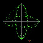
Figure 5 - Crossed Ellipse
Indicator
One of the ellipses tracks the
mark signal and the other ellipse tracks the space signal.
If the signal is far from the selected mark and space
frequencies, it may be difficult to judge from the Crossed
Ellipse display which direction to tune the transceiver to
center the FSK signal. As an aid, there is a small display
inside the the indicator in Figure 5 under the ellipses.
You will find a small vertical red line that indicates the
center frequency between the selected tone pair. If the
RTTY signal is strong, you will see two flashing yellow
dots. One of the dots corresponds to the received mark
signal and the other yellow dot shows the space signal.
Tune the transceiver so that the two yellow dots straddles
the red line. When you are close enough, the crossed
ellipse indicator will provide the indicator to accurately
center an RTTY signal.
RTTY Tone Pairs
When receiving an FSK signal, the transceiver translates
the mark and space carriers to an audio frequency tone
pair. Refer to your transceiver's manual for the preferred
tone pair frequencies.
The tone pair portion of the RTTY control panel (repeated
below in Figure 6) just to the left of the Crossed Ellipse
indicator allows you to customize the mark frequency to
match your transceiver's.
As seen in the figure below, cocoaModem represents the tone
pair by the Mark frequency and the Shift (the shift, as
explained earlier, is the difference between the mark and
the space frequencies).
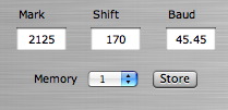
Figure 6 - RTTY Tone-Pair
Selection
cocoaModem comes preset with
the following tone mark tones and shifts in the four memory
locations:
2125 Hz Mark with 170 Hz shift (“North
American” standard),
2100 Hz Mark with 200 Hz shift (200 Hz shift TNCs),
1415 Hz mark with 170 Hz shift (for receivers whose filters
are centered at 1500 Hz) and
1275 Hz mark with 170 Hz shift (“European”
low-tone or mid-tone standard).
You can select one of these using the memory popup menu.
Changing the Mark, Shift and
Baud rate fields will immediately change the tone
pair and data rate that is currently used in cocoaModem (as
usual, remember to type a tab or a carriage return when you
have finished changing a Cocoa text field). These values
are not permanently saved until the Store button
is clicked; the next time you change the memory menu, the
pairs that are save to the plist will reappear.
If you want to replace one of the above pairs by a
different tone pair, simply select a memory address of the
tone pair which you want to overwrite, then replace the
Mark and Shift fields with your own custom frequencies.
Finally, click on the Store button. This should
replace an existing tone pair with your custom tone pair.
All “stored” tone pair sets are saved to your
preference file when you quit cocoaModem and will be
restored the next time you launch cocoaModem. The most
recent menu selection is also saved to the plist when you
quit cocoaModem.
Notice that I have included a 2100/2300 tone pair (2100
mark and 200 Hz shift) in the cocoaModem default set.
If the shift of a transmitted FSK signal is different from
the Shift that is used by the demodulator, the two ellipses
in Figure 5 will not be at right angles to
one another. many ops are still using hardware TNCs as
modems. To reduce costs, some TNCs would use the 200 Hz
Pactor shift even when operating in RTTY. There are also
FSK transmitters where the shift can drift with time.
Most modems, likewise cocoaModem, will print signals whose
shift is off from the standard. However, under marginal
conditions, you can obtain slightly better print (and they
from you) if the two shifts match exactly.
Reversing the RTTY Tone
Pairs
By convention, the Mark tone is the lower of the two audio
frequencies of a tone pair. When this is passed through a
LSB transmitter, the relation of the tone pairs reverses
and the Mark carrier becomes the higher of the two RF
carriers of the RTTY signal.
(Notice that the same can be achieved by making the Mark
tone the lower of the two audio tone pair and using a USB
transmitter instead of an LSB transmitter.)
There are times when the station you are copying is not
following the standard convention but transmit
“inverted” or “reversed” tones. (A
good RTTY operator will switch the tones back to normal
polarity when they are informed that they are transmitting
“inverted” or “in reverse.”)
If a signal is strong and yet not printing anything
meaningful, and the crossed ellipse indicator is spending
more time on the average drawing the vertical oval (the
Space oval) than in the horizontal oval (the Mark oval),
then there is a good likelihood the received signal is
inverted. It is easy to quickly switch cocoaModem’s
demodulator to copy an inverted signal by clicking on the
Rx Polarity button that can be seen on the far
right of the RTTY Control panel in Figure 4. Remember to
click it back to normal when you are through with that
station, or you will have problems with copying normal
stations.
There are times when the operator on the other end both
transmits and receives in reverse. (It happens surprisingly
often when it is some rare DX that you need!) This is a
case where you too will have to swap your transmitted mark
and space tones. This can be done by turning the Tx
Polarity button to Reversed.
RTTY Baud Rate
The baud rate used by radio amateurs is typically 45.45
baud, usually call simply “45 baud.”
Occasionally, someone will use other baud rates such as 50
or 75 baud. To switch to these rates, just enter the number
into the Baud field (Figure 6).
RTTY Squelch
cocoaModem does not use a traditional audio squelch that is
keyed off of the signal strength.
cocoaModem has a unique demodulator in which the Mark and
Space signals are passed through 15 separate automatic
threshold correction (ATC) functions. Traditional FSK
modems use a single ATC.
Each of cocoaModem’s ATC has a slightly different AGC
time constant or a different Mark/Space time delay
(equalizers).
The resultant 5 data bits from each of the ATC function are
sent to a voting unit before it is passed on to the Baudot
decoder. The voting unit determines not just what bits come
from the majority of the ATC, but also how many of them
disagree with the majority.
After a vote is taken, the character can be rejected if
there are too many disagreements. cocoaModem’s
squelch control (Figure 7) selects the error threshold for
when a character is rejected from printing. When the
squelch slider is all the way to the right, all characters
are printed no matter how many ATC are in disagreement.
With the squelch slider all the way to the left, only
characters where every ATC is in agreement will be printed.

The squelch slider in the basic
RTTY interface is located on the right of the receive text
view (see Figure 3).
Bear in mind that this does not mean that every printed
character is guaranteed to be correct when the squelch
slider is pushed all the way to the left. Large noise
pulses could cause all ATC to demodulate into the same bit
pattern, for example – their outputs may agree and
they could all be wrong. All that is guaranteed is that
with the slider moved all the way to the left, characters
that are printed have a greater likelihood of being correct
than a printed character with the slider to the right.
The reason that this multi-ATC squelch also works as a
general squelch is that when a signal is absent, the energy
in the Mark and Space channels are about equal, and as such
the relative delays between the Mark and Space channels
will produce very different results. With the slider push
all the way to the left, for example, will cause all the
characters to be suppressed, since not all ATC will be in
agreement.
If you are new to cocoaModem, it is best to push the
squelch slider all the way to the right. This will cause
all characters to print. Later, you can adjust the squelch
control to suit your needs. With the control moved towards
the left, fewer noise hits would “print.”
RTTY Reception
Once an RTTY signal is perfectly tuned in, characters
should start “printing” into the receive text
view. You can scroll the text view using the scroll knob,
or if you have a scroll wheel mouse, using the scroll wheel
of the mouse while the cursor is inside the text view. Be
sure that cocoaModem is the active window by clicking on
the brushed metal regions if you have selected the brushed
metal interface, or by cicking on the title bar of a
non-brushed metal interface.
If you do not see any print, check the squelch control that
is mentioned above. If the print is garbled, it is
also possible that the signal could be reversed. As described earlier, you can
copy a reversed signal by engaging the Rx Polarity
button. If you find that the majority of the signals can
only be copied in the reversed position, it is quite
likely that you are the one who is operating in
reversed! Please check to make sure that the USB/LSB
popup menu in the RTTY Config panel is set to the
sideband that your transceiver is using.
RTTY Transmission
The transmit text scroll view is below the receive text
view. This is where the text that you enter through the
keyboard goes into the transmit buffer to be transmitted.
Transmit Buffer
When text is inserted into the transmit text view in the
RTTY window, either from the keyboard or from macros, it
enters a transmit buffer and stays there until every
character has been transmitted. If the RTTY modem is not in
the transmit state, the characters simply stay in the
buffer until the next time the transmit state goes active
(or until the buffer is flushed). When a character in the
transmit buffer is transmitted, the character is also
echoed to the receive text view. The color of the echoed
text can be chosen to be different from the color of the
other texts in the RTTY window (see Text Attributes and
Copying Texts in Text Views in the General Information section).
Transmitting Text
To start transmitting the contents of the transmit buffer,
press the Transmit button (Figure 8) to the right of the
text views.
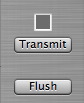
Figure 8 - RTTY Transmit
Indicator, Transmit Button and Flush Button
When the Transmit
button is pressed, the caption of the button changes to
Receive and the color of the small indicator above
the button turns red, indicating that you are now
transmitting (i.e., putting out a tone on the audio output
device). Clicking on the button (that has turned into
Receive) will return you to the receive mode.
Whenever you are in transmit mode (when the red indicator
is on) and the transmit buffer is empty, cocoaModem will
insert an RTTY diddle into the character stream. This is
the beedle-beedle tone that you hear from RTTY stations
when nothing is being typed. Some people do not send
diddles, and the idle station would send a steady Mark tone
instead. Diddles are preferred since it is a way for others
to accurately tune you in when you are transmitting but not
typing. Further, it uniquely identifies the transmission as
an RTTY signal.
When characters are entered into the transmit scroll view,
the new characters will replace the diddles and be
transmitted instead of the diddles. Characters can be typed
directly into the transmit view, or they can be entered
through the use of macros.
Any text that is typed ahead that has not yet echoed to the
receive view can be cancelled by the Flush button
that is beneath the Transmit button. Once a
character is echoed to the receive view, its Baudot
representation has already been transmitted on the air and
cannot be "erased." Unlike the Varicode that is used in
PSK31, there is no backspace character in Baudot. RTTY ops
often type XXX to indicate an error in sending much like a
CW op uses dididididit.
The Flush button does not end the transmission. If you are
in transmit mode, cocoaModem will resume sending diddles
after a Flush. If you’re typing ahead when you are in
the RTTY receive mode, cocoaModem simply wipes the entire
transmit buffer clean. Flush will also remove any
text macros you have inserted into the transmit buffer.
Exiting the Transmit
Mode
To return to the receive mode, press the Receive
button (which was the Transmit button before you
started transmitting).
If there is still untransmitted text in the transmit
buffer, cocoaModem remains in the transmit mode: the red
indicator will turn yellow until the last character in the
transmit buffer has been transmitted. cocoaModem has
returns to receive mode when there are no more characters
in the transmit buffer, and the indicator will also be
grayed out.
You can also use keyboard shortcuts to switch between
transmit and receive modes. And there is a keyboard
shortcut that you can use when in transmit mode to flush
all characters in the transmit buffer and return
immediately to the receive mode. (See Using Keyboard
Shortcuts to control Transmit/Receive in the General Information section of the
manual.)
Back to the Main RTTY page.
Dual RTTY Interface
page.
Wideband RTTY Interface page.