
cocoaModem CW (Morse) Interface
Kok Chen, W7AY
[w7ay (at) arrl
(dot) net]
Last updated: November 16, 2009
Index (User's Manual - CW (Morse) Interface)
General Information
Aural Monitor
Accessibility (Incremental Speak and Voice Assist)
Macros
RTTY Interfaces
PSK Interface
MFSK Interface
Hellschreiber Interface
CW Interface
- Introduction
- Requirements
-
Operation
ASCII Interface
HF-FAX Receiver
Synchronous AM Receiver
Versions
Part II
CW Interface
Introduction
cocoaModem implements a wideband interface that allows you to operate CW within a waterfall's passband.
Although Morse Code is primarily intended for aural reception, the CW interface also provides a Morse decoder for printing moderately strong and well-keyed signals.
For aural reception, the CW interface provides a way to very quickly and accurately zero beating to a CW signal. An Aural tab in the CW Configuration allows you to select a sound output channel that you can connect a pair of headphones to listen to the processed CW signal.
No matter where the signal is on the waterfall, when you click on it, cocoaModem will mix it down to a constant pitch which you can also define in the Config panel. The aural channel can also be selected to listen to the original wideband signal together with a panoramic wide mode.
The "click buffer" is implemented in the auto decode side of the receivers. The aural side will always listen to real time input no matter where you have clicked in the waterfall (it does not make sense to play back a click buffer audio at 8x speed to the aural channel; most people cannot copy 200 wpm by ear).
For CW transmission, cocoaModem implements emission type J2A (see FCC Part 97.3(c)1). J2A is basically what is used in cocoaModem's Feld Hell implementation.
An audio Morse signal, at the same audio pitch as the received Morse signal, is generated and sent to an SSB transmitter that operates in "AFSK" mode. If the transmitter is operated properly (i.e., not over-driven and with no ALC) the emitted signal is indistinguishable on the air from directly keying the transmitter's VFO using an on-off signal. I.e., simply use the same transceiver settings that you use with cocoaModem for RTTY, PSK or Hellschreiber operation -- do not switch your transceiver to CW mode.
(J2A is also used by the HSCW operators for amateur meteor scatter work.)
Requirements
The transmit section of cocoaModem's CW interface will not work with VOX-based push-to-talk (PTT) implementations such as the SignaLink interface or most transceivers' built-in VOX interface.
None of the usual VOX interfaces are fast enough to engage the PTT for the leading Morse element(s) if the PTT has previously been released. cocoaModem's Feld Hell mode implements a dither which periodically sends a dot to keep a VOX mechanism alive, but extraneous dits will not work with an aural mode such as CW.
To transmit from the cocoaModem CW interface, you would either have to use the transceiver's own manual PTT, a serial port driven PTT using cocoaPTT, or a microHAM keyer's PTT through the µH Router. If MacLoggerDX supports PTT through the CAT interface of your transceiver, you will also be able to use that.
Like the other digital interfaces in cocoaModem, the CW interface takes audio data from an input sound device, and it sends the transmit signal through an output sound device. If you intend to use the aural channel, you will need to dedicate a separate (preferably stereo) output sound device that is not the same one being used for the transmit signal. If you are using a dedicated sound card for the transmit signal, you can use the built-in headphones output of the computer, for example.
Operation
Figure 1 shows the components
of the CW Interface.
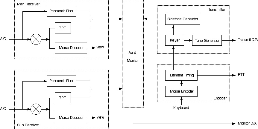
Figure 1 - CW Interface
Components
As shown in Figure 1, there are two identical receiving
interfaces. Each one can be connected to the same A/D
converter (audio input) or a separate A/D converter for
split operation. There is a common transmitter whose tone
can be matched to either receiver's waterfall selection.
Each receiver mixes the input signal to a complex (I and Q)
baseband signal, which is passed to a Morse decoder. The
same signal is mixed with a constant (user selectable)
pitch and then passed through a bandpass filter. The
bandwidth of the bandpass filter is selectable between 30
Hz and 1 kHz. The result is passed to the Aural Monitor
section.
Instead of selecting the narrow band filter, the wide band
input from the A/D converter can be passed directly to the
aural monitor. A panoramic filter can be applied to the
wide band signal. The panoramic filter is essentially a
lowpass/highpass filter pair where one filter feeds the
left stereo channel of the audio monitor and the other
filter feeds the right stereo channel.
The transmit section has a sidetone generator (whose pitch
is also selectable) that is also passed into the aural
monitor.
Fig 2 shows the cocoaModem CW interface while it is
printing a moderately strong CW signal.
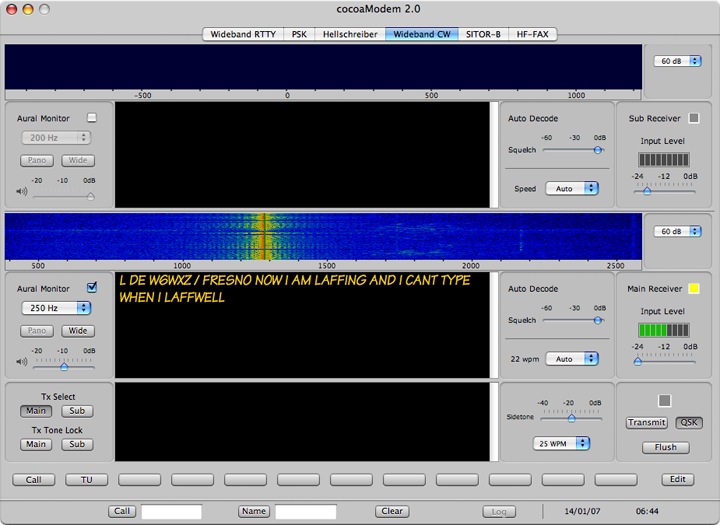
Figure 2-
Wideband CW Interface
Receiver Section
As mentioned above there are two identical receiver
sections in the Wideband CW Interface. Figure 3 shows one
of them in greater detail.
The two receiver sections are called Main Receiver
and Sub Receiver (on the right of Figure 3,
halfway from the top). There is a Transmit Select
indicator next to the receiver name. This indicator turns
yellow if the particular receiver's waterfall click is
selected as the transmit frequency. The selection is done
in the transmitter section. The input level and input
attenuator have identical functionality with the other
modems. (Keep in mind that not all sound input devices have
a digitally controllable attenuator -- the digiKEYER, for
example is controlled by a front panel knob and there is no
attenuation that CoreAudio can see.)
Each receiver is completely independent from the other. The
audio input to the receivers are selected in their
respective tabviews in the Config panel. You can
choose to use the same input sound device, a different
input device, or to use the left channel of a stereo device
for one receiver and the right channel of a stereo device
for the second receiver.
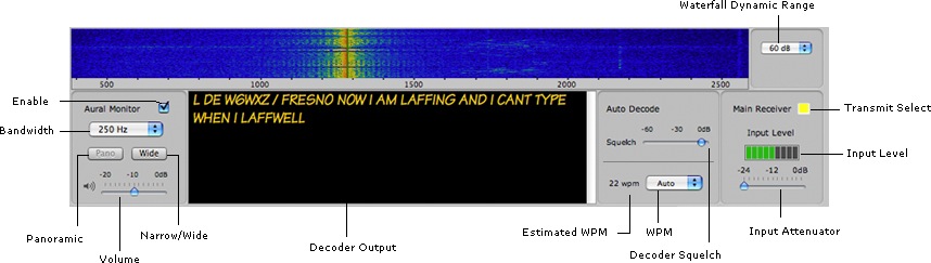
Figure 3 - Wideband CW Receiver
Section
The top of each receiver
section consists of the familiar waterfall display. There
are four receiver control groups below the waterfall
display. The leftmost group are controls for the Aural
Monitor. To the right of that is the text from the Morse
decoder. To the right of the text view are controls for the
Decoder and finally, the familiar input level meter and
input attenuator.
Please note that cocoaMdem's common Aural Monitor controls the
maximum audio volume. The volume sliders in the CW
interface allows you to fine adjust the CW aural output
up to that maximum.
Waterfall Display
As with the other interfaces in cocoaModem, the frequency
scale under the display depends on the VFO Offset
and the AFSK LSB/USB popup menu settings in the
corresponding configuration panel. If those parameter are
set to agree with your transceiver's settings, the precise
frequency that you are receiving and transmitting can be
found by directly applying the offset in the waterfall
scale to the VFO dial display of the transceiver.
If you select a zero VFO offset and set the popup menu to
AFSK USB in the receiver's config, the scale under
the waterfall will show the actual pitch of the audio
signals. (A zero VFO offset with LSB will show the same
scale but in negative frequencies.)
The popup menu to the right of the waterfall selects the
dynamic range of the display.
Aural Monitor
As shown in Figure 1 above, the Aural Monitor
section takes audio input from the aural channels of the
two receivers and the sidetone generator of the
transmitter. The aural monitor is intended for be used
with a pair of stereo headphones that are connected to
an audio output device that is independent of the audio
output device that is used by the transmitter. The
device is selected in the Aural tab of the CW Config panel.
If the Aural Monitor is set to active in the
Config panel, the aural output of each receiver will be
heard unless they are individually disabled by turning off
the Enable checkbox shown in Figure 3.
With the aural checkbox enabled, the popup menu (shown
selected to 250 Hz in Figure 2) chooses the
bandwidth of the audio bandpass filter. You can select a
bandwidth between 30 Hz and 1000 Hz if the Wide
button is not depressed. The pitch of the tone is specified
in Aural configuration.
When the Wide button is pressed, the receiver's
aural channel will be listening to the entire audio
passband from the transceiver instead of listening to the
filtered signal in cocoaModem's CW demodulator. When
Wide is selected, the Pano button selects
the panoramic mode. In the panoramic mode, signals on the
left of the waterfall will sound louder on the left channel
of the Aural Monitor. The lower pitched tones will appear n
the left of the waterfall if USB is selected and on the
right of the waterfall if LSB is selected in the receiver
config. There is a Reverse checkbox in the Aural
config in case the headphones are wired in reverse.
There is a master volume control in the Aural config panel.
The slider at the bottom of the aural control group allow
the independent adjustment of the volume from each
receiver.
There is no "click buffer" in the Aural channel, what you
hear will be the current data samples even if you were to
click on the top of the waterfall. The click buffer works
on a principle that when clicked, the sampling rate from
the buffer is raised by a factor of 8 until it has finally
caught up with the real time data. Copying the click buffer
by ear at 200 wpm is simply unrealistic.
Morse Decoder
The CW interface provides a Morse decoder to print
well-keyed signals that have a good signal to noise ratio.
The Auto Decode section in Figure 3a shows the three basic
controls, the decoded output goes to the textview in Figure
3.
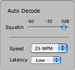
Figure 3a -
Auto Decode Section
If the baud rate menu is set to
Auto, the CW interface will attempt to figure out the
keying (word per minute) speed. This will only work well
with a clean and steady signal and may take a few seconds
to lock in after clicking on a signal (cocoaModem may
implement a multiple demodulator in the future to make this
process faster, but it is not currently a high priority
item for me). If a fixed keying rate is selected from the
speed menu the CW interface will allow about 20% of speed
tracking to occur. The speed readout to the left of the
popup menu indicates the estimated speed once the interface
finally locks on to the signal.
The automatic CW decoder has some pipelines built in to
take care of noisy or poorly keyed Morse characters. This
can cause the characters to appear much later than they
were received. A Latency popup menu controls the
amount of post processing.
The latency menu can be selected to use low
latency (least post processing), medium and
high latency (most post processing). You might
prefer to use low latency for chasing DX and high latency
for ragchews and printing news bulletins, where accuracy is
more important than latency.
The Morse Decoder takes its input from the familiar
wideband "click buffer." If you click higher up on the
waterfall, more of the history will be decoded. You can
thus decode the trace of a signal in the waterfall that has
stopped transmitting.
Transmitter Section
Figure 4 shows the transmitter section of the CW Interface.
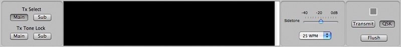
The Tx Select buttons
chooses where the transmitter gets its frequency from. When
Main is selected, the transmitter will take the frequency
from the Main Receiver of the CW Interface.
The Tx Tone Lock buttons can be useful if you are
a CQing or a net control station.
The Tx Tone Lock behaves a little differently from
the Wideband RTTY interface. In the RTTY interface, the Tx
Tone Lock locks the transmitter to the default tone pair
for the receiver. With the CW Interface, the Tx Tone
Lock locks the transmitter frequency to the receive
frequency that was in use at the time when the tone lock
button is depressed.
When locked, the green marker in the waterfall no longer
moves and continues to indicate the transmit frequency.
When you click on the waterfall to receive stations at
other frequencies, a magenta marker will appear on the
waterfall to indicate the received frequency (this is the
same behavior of the Wideband RTTY waterfall).
You can lock the transmit frequency for either or both of
the receivers.
The text view displays the text to be transmitted. Any text
typed into this view will remain in the transmit buffer
until either the Transmit button or the QSK button are
depressed, or if Flush is depressed to remove the contents
of the characters in the buffer. If you are already
transmitting, the Flush button will stop transmission at
the Morse element level. Unlike the RTTY and PSK
interfaces, it will not wait until a character has finished
going out before stopping.
The risetime and weights of the keying signal can be
defined in the Transmitter Config panel. The
Farnsworth slider changes the intercharacter spacing of
the Morse element to reduce the actual word speed of the
Morse transmission while keeping the character speed at
the speed that is selected in the menu in Figure 4
above. Unless there is a reason to change these
settings, simply leave them alone. The Default
button will set the settings back to the nominal values.
Waveshaping
cocoaModem uses a Blackman window to shape the keyed signal
(most of the other FIR filters in cocoaModem are also
Blackman windowed or modified-Blackman windowed). Figure 5
shows the spectrum of the transmitted signal (a sequence of
dits) with the default 5ms selected in the risetime slider
(the horizontal scale is in Hz and the vertical scale is in
dB). The signal will not remain this clean of course after
it passes through the SSB modulator of the transceiver, but
Figure 5 shows how keyclick free the signal can potentially
be. Make sure you do not overdrive the audio stages of your
transceiver and also make sure there is no ALC
activity.
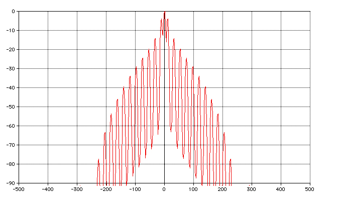
Figure 5 - Keyed
Spectrum
As usual, the Macro buttons
will expand macros into the transmit buffer.
And, as usual, the Command-T, Command-R and Command-X
keyboard shortcuts can be use instead of the the
Transmit/Receive and Flush buttons.
Semi Break-in
There is a semi break-in facility in the CW Interface. If
the QSK button is depressed, any text that you
type into the transmit view will cause the PTT to engage
and the text to be immediately sent after pausing for the
amount defined by the PTT lead-in time. The PTT lead-in and
release times are set in the Transmit Config panel. With a fast
Macintosh, a 10 ms lead-in is more than sufficient to
apply PTT through the µH Router and a digiKEYER that is
connected to a FT-1000MP transceiver. For other PTT
device combinations, adjust this number so that there is
sufficient time for the first Morse element to
consistently be transmitted to a dummy load when
cocoaModem's CW QSK is engaged.
The PTT release time determines the amount of time that has
passed after the last Morse element has been sent before
the PTT is released by cocoaModem. cococaModem will not
work with full break-in (T/R switching in between Morse
elements) - do not try to set the release time to too short
a value.
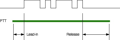
Figure 6 - Semi-break-in
PTT Timing
Configuration
Like other interfaces, the configuration of the CW
Interface is done by bringing up the Config panel. The
Config panel is opened by using the Config item under the
Window menu in the Menu Bar, or using the keyboard shortcut
Command-Option-Comma.
The config panels for the Receivers are similar to the
other interfaces but the Transmit and Aural config have
addition items that are not in the other interfaces.
Transmit Config
Figure 7 shows the Transmit configuration.
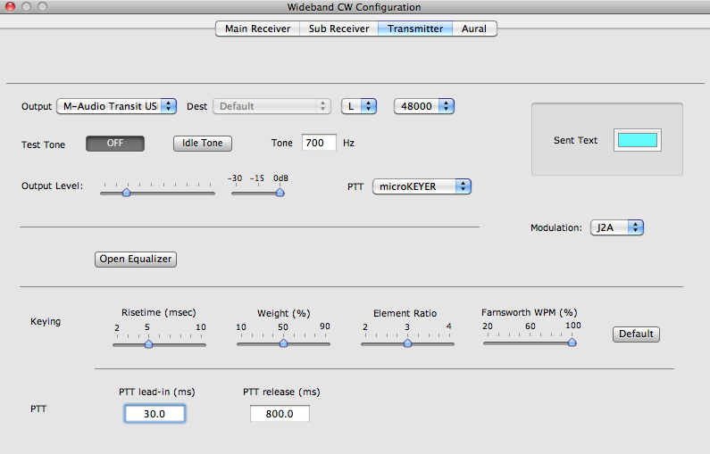
The Transmit Config panel
includes parameters to control the transmit keying.
The Risetime slider controls both the rise and the
fall time (symmetric in cocoaModem's CW interface) of a
pulse. cocoaModem uses a Blackman window to shape a keying
pulse. The window width is adjusted to give the equivalent
risetime (defined as the time from 10% to 90% of a leading
edge of a pulse). Figure 5 shows the spectrum of a
sequence of pulses with a 5 msec risetime -- which is a
good compromise to 40 wpm. For a harder keying, the
Risetime slider could be brought lower but be
aware that the bandwidth of the CW signal will also
increase proportionately. For speeds less than 15 WPM,
the rise time can be increased somewhat, to reduce
spectrum occupancy, without the signal sounding too
soft.
The Weight slider controls the ratio of the
duration of a dit to the duration of an inter-element space
(the space between the dits and dahs of a Morse character).
With the Weight slider set to 50%, the duration of
a dit is the same as that of the inter-element space. This
is the standard Morse weight. With the Weight
slider set to 90%, the duration of a dit is nine times
longer than the duration of the inter-element space.
The Element Ratio is the ratio of the duration of
a dah and the duration of a dit. The element ratio is three
for standard Morse.
Farnsworth spacing is really only use for Morse
practice (this allows cocoaModem's CW Interface to be used
as a Morse trainer by routing the transmit sound output to
a speaker). Farnsworth spacing allows the element spacing
to run at a given speed while the character spacing running
at a slower speed. The character spacing (normally 3 times
the duration of the inter-element spacing) is increased in
Farnsworth spacing. When the Farnsworth slider is
set to 20%, the character speed will be 5 times slower than
the speed that is selected in the main window) -- i.e.,
with the actual speed set to 25 wpm and the
Farnsworth slider set to 20%, the Morse will be
keyed so that the character rate is the same as a standard
5 wpm signal.
The Default button resets all the siders to the
default value that cocoaModem started with.
As mentioned earlier, there is a semi-break-in
mechanism. The PTT lead-in and Release parameters are
defined in the Transmit Config panel shown at the bottom
for Figure 7.
Modulation (J2A/OOK)
selection
The Modulation menu on the right of Figure 7 lets
you select between generating audio that is meant for J2A
transmission and generating an on-off keying (OOK) tone for
driving devices such as the microHAM USB Interface III.
When you select J2A mode, cocoaModem
outputs a keyed audio tone to modulate an SSB transmitter.
The SSB transmitter will translate an audio pulse packet
into an RF pulse packet -- the result will appear as an RF
CW signal that is identical to one that is generated by
using A1A (keyed carrier) emission mode.
As mentioned earlier, a waveshaping window is applied to control
the bandwidth of the RF signal on the air.
Alternately, cocoaModem can be used to output a keyed audio
tone which an external interface can decode into a keyed DC
on-off signal for use with A1A transmitters. When used in
this manner, no waveshaping is required since any
waveshaping of the RF pulse will be performed by the A1A
transmitter itself. Waveshaping the keyed audio signal can
contribute to jitter at high Morse speeds.
If you choose OOK, cocoaModem outputs a
keyed 2500 Hz audio tone with fixed amplitude and no
waveshaping. Please note that when you use OOK, you lose
the frequency agility of the waterfall. You can still click
on the waterfall to receive different signals, but the
transmitted signal will be fixed by the VFO of the A1A
transmitter itself. The amplitude of the tone is about -3
dB (relative to full scale) of the sound card.
The microHAM USB Interface III and the K4DSP Regenerator
both support this tone keyed method for generating a CW
keying signal.
Since the OOK audio signal has no waveshaping, you must not
use the OOK audio to directly modulate an SSB transmitter.
Doing that will result in key clicks that can be heard many
kHz away. Use the J2A mode when audio modulating an SSB
transmitter.
Aural Monitor
Config
Figure 8 shows the config panel for the Aural Monitor.
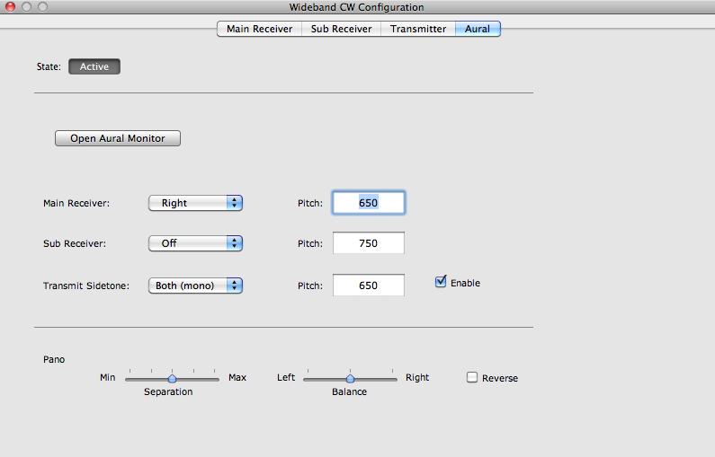
Figure 8 - Aural
Config
The Open Aural Monitor
button opens the common Aural Monitor in cocoaModem.
All audio from the CW Aural Monitor are sent to the
sound card that is sected by the common aural monitor.
If you don't require any audio feedback, keep the state
button in the Inactive state. If you turn the
button active, make sure that the output is not using
the same device as the one used in the CW Transmitter.
The Aural Monitor takes the outputs from the two receivers
and the transmit sidetone and mixes them to provide output
to a pair of stereo headphones.
With the popup menus in the Aural config, you can
optionally choose to send each of the three sources to
either or both stereo channels of the output.
Additionally, you can distinguish between the channels by
selecting different pitch for the transmit sidetone and the
pitch of the receivers when the narrow filters are
selected.
The receivers can individually be disabled in the main
window and the tranit sidetone can be disabled with the
Enable checkbox shown in Figure 8.
Panorama Audio
When a receiver's aural monitor is set to wide, you have
the option of choosing to listen to it in the panoramic
mode.
In the panoramic mode, the signals on the left side of the
waterfall will sound louder on the Aural Monitor's left
headphone than the signals that are on the right side of
the waterfall. The opposite is true for the right
headphone. The Pano Separation slider lets you
adjust the blend and the Balance control
compensates for your ears' frequency response. The
Reverse checkbox allows the headphones to be wired
in reverse.
Extending the Morse
Alphabet
You can extend the standard Morse alphabet in cocoaModem by
including them in a text file called Morse.txt in
the Library/Application Support/cocoaModem folder
of your home directory. Create the file and folders if they
don't already exist. The text file can be created using
standard text editors such as TextEdit.app.
For each new character in the alphabet, you will need to
add one line of text. The line starts with a decimal number
that corresponds to the ASCII or Unicode correspondence of
the keystroke. That should be followed by at least one
space or tab character, and then followed by a string of .
(period, standing for a dit Morse element) and - (minus,
standing for a dash Morse element) that makes up the Morse
character. For example, the following will place the .-.-
sequence at the ä and the Ä positions of the keyboard. On a
US keyboard, ASCII 228 and ASCII 196 are equivalent to
typing option-U followed by an 'a' or an 'A'.
228 .-.- // a with
umlaut
196 .-.- // A with umlaut
Notice that you can include a comment after the Morse
definition by including some space characters between the
morse sequence and the comment. Notice too from the example
above that the code needs to be repeated for both upper and
lower cased ASCII if you want both the upper case keystroke
and the lower case keystroke to send the same code.
Each . is sent as a Morse dit followed by an inter-element
spacing (for standard Morse, the inter-element spacing has
the same duration as a dit; in cocoaModem, you can modify
this ratio globally with the Weight slider in the
transmit config panel).
Similarly, a - is followed by a single inter-element
spacing whose duration is nominally the length of a dit.
The length of a dah is nominally three times the duration
of a dit but can be globally modified with the Element
Ratio slider in the transmit config panel.
You can change the weights of elements and inter element
spacing specifically for each character in Morse.txt.
Each vertical bar (|) character will add an addition 1/2 of
inter-element spacing to the existing inter-element
spacing. Two bars (||) will add a full inter-element
spacing to the original spacing, etc.
If you use a * instead of a period character, a dit that is
50% longer than a regular dit will be generated. A =
instead of a - generates a dah that is 50% longer than a
standard had.
As example, the following line
8776 *||*||*||*||*||*
will generate six dits. Each dit is 50% heavier than a
standard dit and the space between the dits are twice
(1+0.5+0.5) as long as a standard inter-element spacing.
The sequence is assigned to the Option-x key (≈ or
Unicode 8776) of a US keyboard.
You can overwrite a standard Morse character by reassigning
an existing standard ASCII slot in Morse.txt.
Prosigns are easily defined in this manner and they can be
assigned to any key on the keyboard.
The same Morse.txt file also extends what is displayed to
the received window. When cocoaModem receives a Morse
sequence that is defined in Morse.txt, the corresponding
ASCII character is sent to the screen. In the case of
receiving text, the ASCII character has to be between 1 and
255 and the sequence must only contain dots and dashes
without stars and vertical bars.
Next (ASCII)