
User's Manual - Part II
Kok Chen, W7AY
[w7ay@arrl.net]
Last updated: Mar 5, 2006
Introduction
cocoaModem was originally written as a software framework for me to experiment with various DSP implementations of digital modulation modes that can benefit from the MacOS X CoreAudio and the Altivec vector (SIMD) processor that are present in G4 and G5 computers. I have decided to make it available “as-is” for others to use.
cocoaModem is written for the Cocoa framework of MacOS X; most of the code is in Objective-C, with some plain C modules where appropriate. The application is built using the Xcode integrated development environment (IDE), and the user interface design is built using the Interface Builder (IB). Xcode and IB comes in the Developer disk which is shipped with every copy of the MacOS X operating system.
The entire cocoaModem Xcode project is freely available to noncommercial developers who would like to add, modify, change UI appearances, use parts of it as sample code for their own projects, etc. Except for the Apple frameworks, cocoaModem does not use any licensed code, whether open sourced or not. cocoaModem is completely homebrewed. Please write to me at w7ay@arrl.net to obtain the project. My primary interest is in modem algorithms, and not user interfaces.
cocoaModem uses Apple’s vDSP library which makes use of, but does not require the presence of Altivec.
I have used this application on various of my computers, ranging from a G3 Powerbook running Jaguar (MacOS X 10.2) to a G4 PowerMac running a prerelease copy of Tiger (MacOS X 10.4) to a dual processor G5 running Panther (MacOS X 10.3).
RTTY
Crossed Ellipse Indicator
The Crossed Ellipse indicator consists of two narrowband IIR filters, one centered at the Mark frequency and the other centered at the Space frequency. With classical implementation of the crossed ellipse indicator, the filters need to have a precise 90 degree phase shift 170 Hz away the center of their passbands. This is what keeps the ellipses orthogonal to one another when a signal is properly tuned. cocoaModem uses graphical transforms to achieve orthogonality, rather than dealing with filter phase shifts that the classical implementations use.
The outputs of these filters are a pair of numbers that represent the x and y axis of a plot (in the old days, the Mark and Space filter outputs are connected to the x and y inputs of an oscilloscope).
As a result, a perfectly placed Mark tone will draw out an ellipse whose major axis is horizontal, and a perfectly placed Space tone will draw out an ellipse whose major axis is vertical. The fatness of the ellipses is determined by the bandwidth of the filters that are used. A narrower set of filters produce thinner ellipses and a wider set of filters produce fatter ellipses.
Narrower ellipses allow more accurate tuning, but can be very confusing when the signal is off tuned. It is easier to identify the direction a signal is off tuned with wider ellipses, but it is harder to tune a signal in precisely. cocoaModem tries to strike a balance between the two.
Spectrum Display
The yellow dots in the Crossed Ellipse display are part of an FFT spectrum (think of it as one line of a typical waterfall display, but using brightness rather than color to indicate the energy at any spectrum bin). The left part of the spectrum line represents a frequency of about 300 Hz and the right part of the spectrum line represents a frequency of about 3000 Hz. How much of the audio bandwidth is visible on this display depends, of course, on the bandwidth that is set on your transceiver. The red line is the midpoint between the Mark and Space tones.
With a strong signal, you should see two yellow dots that flicker about. These are the Mark and Space tones of the signal. Tune until the yellow marks straddle the red line, and the crossed ellipse should take on a familiar pattern that can be used to fine tune with.
(not yet) The little button at the bottom right of the tuning indicator is for switching the crossed ellipse to an indicator that is based on a little known demodulator that was originally proposed by Claude, DJ0OT ca 1990. DJ0OT’s demodulator and the accompanying indicator is based upon placing zeros rather than poles at the Mark and Space tone centers...
RTTY Monitor
For diagnostic purposes and for those interested in the nuances of FSK signal processing, there is a special instrumentation panel for monitoring RTTY signals as they go through the various stages of FSK demodulation.
The RTTY Monitor panel is opened by selecting the RTTY Monitor item from the Window menu in the Menu Bar. To close the RTTY Monitor, use the standard window close button at the top left corner of the RTTY Monitor panel.
The RTTY Monitor can display a waveform or a spectrum at various stages of RTTY demodulation. The stages that can be monitored is selected from one of the buttons at the bottom of the RTTY Monitor panel. The monitor can select between the Input from the sound A/D converter, the output of the Band Pass Filter, the output of the Matched Filter, the output of the Automatic Threshold Control (adaptive slicer) and the bit sync output (after the start bit of a character has been identified).
Figure 1 shows the RTTY Monitor displaying the matched filter output of a clean RTTY signal after the adaptive threshold correction. If you are familiar with how matched filters work, you can see the matched filter integrating to a peak at the end of each bit period.
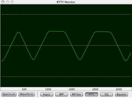
Figure 1 - RTTY Monitor
RTTY Diddles
The so called idle or diddle character is not a fixed code. Among the more popular non-printing characters used as diddle characters are the Baudot NULL character and the Baudot LTRS character. cocoaModem uses the LTRS character as the diddle character.
Appendix A – RTTY, FSK and AFSK
Introduction
Amateur Radio RTTY (“radio teletype”) is a digital mode that uses Frequency Shift Keying (FSK) as the modulation scheme. An FSK signal is made up of a pair of carriers, only one of which is on at any instant. Traditionally, the higher frequency carrier on the RF spectrum is called the Mark frequency and the lower frequency carrier on the RF spectrum is called the Space frequency.
The separation between the two carriers is called the “shift.” In Amateur RTTY, the standard shift is 170 Hz. Other services, such as news wires, may use a different shifts. Amateurs also occasionally use wider shifts such as 850 Hz, but the use of wide shifts are quite rare. When operating in AFSK, you can pick arbitrary shifts in cocoaModem since the mark and space frequencies can be independently set.
The reason the Mark frequency was chosen as the higher one stems from the way the shift was generated in “the old days.” Before the days of direct digital synthesis transceivers, FSK was generated by a single oscillator that is keyed between the Mark into the Space conditions by the addition of a small capacitor. The “rest” position of RTTY is the mark and the capacitor is switched in whenever a space bit needs to be transmitted – this shifts the oscillator to a lower frequency, making the space frequency lower than the mark.
To reduce expense, some Terminal Node Controllers (TNC) designed primarily for Pactor but sold as also supporting (the word “support” is obviously used loosely here) RTTY have implemented RTTY as 200 Hz shift. Under good conditions, 200 Hz shifts signals can be copied by 170 Hz equipment and vice versa, but it is not ideal under weak or poor conditions.
A character stream, encoded in the 5-bit Baudot code is used to key the modulator between the Mark and Space carriers. A “one” bit in the Baudot code is transmitted as a Mark signal and the “zero” bit in the Baudot code is transmitted as a Space signal.
To achieve character synchronization, a start bit (Space) immediately precedes each 5-bit character code and a stop bit (Mark) immediately follows it. The system stays in the Mark position until the next character comes along. The stop bit “latches” the system from any further decoding and the start bit “releases” the latch.
The start and character bits in Amateur RTTY are 22 ms in duration. The data rate is thus 45.45 baud, sometimes also known as a data rate of “60 words per minute” (60 WPM) and often shortened to “45 baud.”
A baud is a measure of data rate, defined as one symbol per second. In our case, a “symbol” is a “bit,” thus RTTY’s 45.45 baud is equivalent to 45.45 bits per second. With a different modulation scheme where each modulation instance can encode more than one bit, a baud can be equivalent to multiple bits per second. For example, Quadrature PSK such as QPSK31 at 31.25 baud transmits data at 62.5 bits per second.
The duration for the stop bit varies. The most common stop bit durations used in 45 baud RTTY operation are 1 data bit time, 1.4 data bit times, 1.5 data bit times and 2 data bit times.
Mechanical teletypewriters require some settling time after encoding a character -- the Model 33 Teletype machine required 2 stop bits to function properly, while the Model 35 required 1.5 stop bits. Computer implementation requires only a single stop bit to function. However, more stop bits can often help with character synchronization in noisy conditions at the expense of slightly slower throughput.
Software RTTY modems commonly allow the selction of one, 1.5 or two stop bits. For various reasons, 1.5 stop bits is the preferred selection. cocoaModem, for example, is most robust when printing RTTY signals that are generated with 1.5 stop bit systems.
The 5 information bits of a Baudot character are transmitted with the least significant bit immediately following the start bit.
Amateurs also use faster rates such as 57 and 75 baud on RTTY. However, like the wider shifts the use of faster rates is also moderately rare.
FSK Demodulation
The two RF carrier frequencies of an RTTY signal are usually demodulated by an SSB receiver into two audio tones. These tones are separated by the same 170 Hz shift as the two RF carriers.
For the “standard” used in the USA, an LSB receiver is tuned so that Mark signal is demodulated into an audio tone with a frequency of 2125 Hz. Since the Space carrier is 170 Hz lower in the RF spectrum, it is demodulated by the LSB receiver into a higher tone of 2295 Hz.
There are other such popular “tone-pairs.” European Amateurs often prefer a lower frequency tone pair of 1275/1445 Hz. Note that the shift remains 170 Hz.
Systems set up for the European tone pairs can decode US Tone Pair by simply tuning the LSB receiver to a point 850 Hz higher in frequency.
cocoaModem lets you set arbitrary tone pairs.
Sometimes, RTTY signals are sent in reversed or inverted i.e., the Mark is the lower frequency signal on the RF spectrum. This can happen through operator error, typically by transmitting an AFSK signal in USB rather than LSB without also reversing the audio AFSK tones.
FSK versus AFSK – what is the difference?
The two most often used methods of generating an RTTY signal are what Amateurs refer to as FSK and AFSK modes. Remember that the main aim of RTTY is to switch between two carriers with known separation, and at a known keying rate.
You can generate an FSK spectrum by directly shifting the frequency of an RF oscillator. This method is usually called “direct FSK,” “true FSK” or simply the “FSK” mode.
Alternately, you can also start by generating an FSK signal in the audio frequencies. For example, switching between two audio oscillators at 2125 Hz and 2295 Hz. This audio signal can then be used to modulate an SSB transmitter, thus translating the two audio tones into two RF frequencies. This method is called “audio FSK” or “AFSK.”
An active RTTY signal that is constantly switching between the mark and space frequencies will also generate sidebands that extend between the two carriers and have sidebands slightly (about 70 to 130 Hz) beyond the mark and space carriers.
When properly operated, one cannot tell the direct FSK or the AFSK methods apart on the air. Very often, one simply says FSK to mean either method, since they both produce an identical frequency shift keyed signal on the air.
The use of AFSK is more predominant with modern SSB transceivers. Even when transceivers have modes that are marked as FSK, they are very often, as in the case of the Yaesu FT-990 and FT-1000D just implemented as internal AFSK generators in the transceivers themselves. These internal AFSK generators are keyed by the “FSK” input line. This mode is often called the “keyed AFSK” mode. Internal to the transceiver, it is just an implementation of AFSK. Externally, as an electrical interface, it behaves as if you are connected to a direct FSK transceiver.
Some of the few modern transceivers that use direct FSK are the Ten-Tec Omni V and VI series transceivers.
How AFSK works
When operating in direct FSK, you switch between two RF carriers, say at 14,080.170 kHz and 14,080.000 kHz. When keyed (i.e., switching between these two carriers) by a 5-bit Baudot data stream, you create a 170 Hz shift RTTY signal.
When operating in AFSK, you also generate a pair of signals. But this pair of signals are generated not at RF but at audio frequencies. The most common audio tone pair that is used is the 2125 Hz and 2295 Hz pair. Notice that the tone separation is again precisely 170 Hz. When keyed between these two audio tones, you create an AFSK (audio FSK) signal. Instead of directly generating the mark signal at 14,080.170 kHz, your AFSK mark frequency is at the audio frequency of 2125 Hz.
If you proceed to modulate an LSB transmitter with this audio FSK signal, the transmitter basically translates the two tones up to two RF carriers in the RF spectrum. Since it is lower sideband transmission, the lower of the two audio tones becomes the higher of the two RF carriers.
A sideband transmitter uses a balanced modulator to multiply a carrier by the modulating audio. In the frequency domain the transmitter effectively convolves the AFSK tone pair with an impulse at the carrier frequency, thus translating the two tones into the RF spectrum. There are two sets of these sidebands, one set positioned below (LSB) and one set positioned above (USB) the suppressed carrier. Through filtering or phasing, one of these sets is removed before the signal reaches the antenna. The carrier itself is suppressed away by the balanced modulator -- thus the nomenclature “single sideband suppressed carrier” (SSB).
If you place the suppressed carrier of an LSB transmitter at 14082.295 kHz, the two AFSK tones at 2295 Hz and 2125 Hz will now appear on the RF spectrum at 14,080.170 kHz and 14,080.000 kHz respectively. This is precisely what you had gotten using the direct FSK method that is described in the first paragraph of this section.
Again this bears repeating since there is always some zealot making unsubstantiated claims on the superiority of FSK: from the spectrum viewpoint, FSK and AFSK are indistinguishable by the receiver when the transmitter is properly operated.
FSK is more forgiving to operator errors since there can be no possibility of overdriving a modulator, or having the microphone accidentally sending voice over the RTTY sub bands.
AFSK, on the other hand has its own set of advantages, such as the ease of controlling and maintaining very precise frequency shifts and the ability to easily wave shape the audio signal to reduce sidebands (similar to wave shaping CW keying to reduce sidebands). cocoaModem implements AFSK modulation that is phase continuous and for additional measure, applies a band-pass filter on the AFSK signal before sending it to the transmitter.
Many of the signals that you receive on the air which have wrong shifts often come from Ten-Tec Omnis -- typically, the trimmer capacitor that is used to offset the FSK oscillator has drifted over time. For the same percentage drift in an AFSK oscillator, the change in frequency won’t even be noticed.
We used an LSB transmitter when discussing the AFSK example above. Instead, if you were to place the suppressed carrier of a USB transmitter at 14077.875 kHz and modulate it with the same AFSK signal as described above, you will again have shifted the tone pairs up to 14,080.170 kHz and 14,080.000 kHz. Except that the resultant tone pairs in the RF spectrum are now reversed. This is easily compensated for by also swapping the audio Mark and Space frequencies. This is what happens in cocoaModem when you select the USB preference.
Where am I transmitting?
Let us assume that you will be using an SSB transmitter in lower side band mode when using AFSK. The default tones used by cocoaModem are 2125 Hz for the Mark tone and 2295 Hz for the space tone. With LSB, this places the two FSK carriers at 2.125 kHz and 2.295 kHz lower, respectively, than the suppressed carrier frequency of the transmitter.
The dial of an SSB transceiver usually reads out the suppressed carrier frequency. When operating RTTY nobody cares what the frequency of your suppressed carrier is, not the FCC, not the DX. With a properly operated SSB transmitter, no one else can tell what the suppressed carrier frequency is.
By convention, RTTY veterans use the Mark frequency as the reference frequency to identify the location of a signal. The mark frequency should be the only frequency that is spotted to the Packet clusters. Spotting the suppressed carrier VFO readout is completely useless information to anyone else unless you also mention whether you are using LSB or USB, and what the AFSK mark tone frequency is!
The better modern transceivers allow you to automatically apply an offset frequency to the VFO display when you are operating in AFSK mode. If this feature is available, the transceiver should be set to report an offset of -2.125 kHz when you operate cocoaModem in LSB, or +2.125 kHz if you are operating in USB. Your VFO dial will then directly display the actual FSK Mark frequency.
If your transceiver does not support a VFO display dial offset, make sure that you subtract 2.125 kHz from the VFO dial readout when you spot a DX if you are using LSB and add 2.125 kHz to the dial readout if you are using USB.
An FSK signal is not just the mark tone, of course. If one considers an RTTY signal to be 260 Hz wide, then the FSK signal is a band of signal which extends from 2.080 kHz below the suppressed carrier frequency to 2.340 kHz below the suppressed carrier frequency (in LSB mode).
Without a VFO offset, if you were to transmit an LSB AFSK signal with the VFO set to 14.102 MHz, you would be completely wiping out the International DX Beacons at 14.100 MHz.
Appendix B – External Hardware
Introduction
cocoaModem needs two pieces of hardware to function. The first is a way to get audio in and out of the Macintosh and the second is a way to key the transceiver into transmit mode.
Audio from an SSB receiver to cocoaModem has to be converted into numerical data streams that represent the audio waveform. These numbers are called data samples, or simply “samples.” The input converters are known as analog-to-digital (A/D) converters or simply sound or audio input device.
cocoaModem also needs to convert numerical streams into audio to modulate an SSB transmitter. The output converters are known as digital-to-analog (D/A) converters.
Some Macintoshes already have built in audio line-in and line-out connectors which perform the A/D and D/A functions. If so, the transceiver can be connected directly to the Macintosh’s audio input and output connectors.
Macintoshes without built in audio line-in and line-out connectors would need an external USB or FireWire Audio adapter. See Appendix B.1 “A/D and D/A Converters” below.
In addition to providing conduits for the analog audio signals, cocoaModem also needs some way to key the transmitter. The audio line-out merely sends an audio signal to the SSB modulator of the transmitter. The transmitter needs to be keyed on to generate an actual RF signal.
cocoaModem keys the transmitter with the VOX (voice operated transmission) circuitry of a transceiver. If the transmitter has VOX capability in the transceiver mode, usually called AFSK or Packet which cocoaModem works with, then you are all set. Just follow the adjustment procedures.
However, many transceivers’ VOX does not function in the AFSK mode (for example, the Yaesu FT-920, FT-990 and FT-1000MP transceivers) and only provide a push-to-talk signaling pin. With such transceivers, you will need an external device that can sense the presence of an audio output from the Macintosh and triggers the transceiver’s push-to-talk signal. See Appendix B.2 “Keying the Transmitter - PTT and VOX” below for more details.
A/D and D/A Converters
Audio signals such as sound from the radio can only be read by the computer as a stream of numerical values, typically at the rate of 11025 samples per second. An analog-to-digital converter (“A/D converter”) is used to convert the audio waveform into such a stream of numbers that the computer can digest.
In the opposite direction, the computer generates audio sounds by sending a stream of numbers to a digital-to-analog converter (“D/A converter”), which converts the numbers to equivalent time varying voltages.
Many Macs already have built in sound devices which provide the A/D and D/A converter functions. These are usually labeled as audio line-input and audio line-output connectors. Often, the audio input is labeled as a microphone input and the audio output is labeled as a headphone or speaker output.
Some Macs, however, only have headphone or speaker output (not the most ideal for low intermodulation transmissions) and microphones that are built into the machines, rather than a stereo jack where you can plug an external microphone or the output from the radio. You need an external A/D converter to get audio samples into these machines.
Even for Macs that have line-in and line-out, these usually come in a fixed format of 16-bit A/D and D/A converters with a fixed sampling rate of 44100 samples per second and also fixed at two channels (stereo).
While the built-in audio devices may be perfectly viable for everyday communications, you can get better immunity against HF conditions such as weak signal, flutter and selective fading by using A/D converters which have 18-, 20- and 24-bits. If you intend to do any DX work, it is highly recommended that you use an external audio device. Among the other advantages of external audio devices are higher dynamic range and lower noise floor.
For Macintoshes that do not have audio line input, the Griffin iMic (www.griffintechnology.com) is one such relatively inexpensive and small USB sound-in and sound-out device. It supports 8- and 16-bit data in and out, with either 1 or 2 channels. The ability to handle a single channel reduces the USB bus bandwidth when the second audio channel is not used by cocoaModem.
Older iMics are capable of 20-bit conversions while the newer generation (Rev3) iMics will only go up to 16 bits. However, I have tested the newer iMics they have a smaller performance hit (a 5 dB noise floor difference) than the 16 to 20 bit differential suggests.
By comparison, the built-in microphone input of a 500 MHz PowerMac AGP which I had tested has a 5 dB noise floor disadvantage when compared with even the 16 bit iMic (i.e., 10 dB worse than the 20-bit iMic).
The iMic also supports various sampling rates. cocoaModem processes data at 11025 samples per second. Most Macs’ built-in audio only support a fixed 44100 samples per second rate and the data in cocoaModem has to go through an extra stage of processing (called decimation, consisting of a low pass filter that is followed by a down sampler) to bring the sampling rate down to 11025 samples per second. The iMic supports many sampling rates and 11025 is one of them.
cocoaModem has tested against an iMic, and it is the recommended audio device for complete plug-and-play with cocoaModem.
Keying the Transmitter – VOX and PTT
Transceivers come with various facilities to key the transmitter. Examples are: a CW key, a Manual Operated Transmit (MOX) button in the front panel, a Voice Operated Transmission (VOX) switch, a push-to-talk (PTT) button on a microphone or a PTT contact on a rear connector of the transceiver, a foot switch connected through the microphone connector, etc.
VOX operates by having circuitry inside the transceiver which detects the presence of an audio signal. When an audio signal is present, the transceiver generates an internal PTT signal to key itself.
The Macintosh has no facility for making contact closures to make PTT operations. You can build a transistor switch, but the switch still has to be triggered by some signal, such as a signaling pin on a serial port. Increasingly, modern machines don’t even come with serial ports. Therefore, for plug and play reasons, I had decided to make cocoaModem require VOX as the standard means of keying the transmitter.
Many transceivers support VOX only in SSB modes -- their VOX circuit do not work when the transceiver is placed in AFSK mode, where the narrow RTTY IF filters can be used. With these transceivers, the transmitter can only be keyed using the PTT signal, usually in the form of a switching signal on a rear panel connector.
In the case of the Yaesu transceivers, the PTT signal is available in a rear panel 5-pin DIN connector called “Packet.” This connector also carries the audio in and audio out necessary for AFSK operation.
If your transceiver does not support VOX in the AFSK mode, you will need an adapter such as the Tigertronics SignaLink SL1+.
The SignaLink is a small box that has a built-in VOX circuitry for engaging a PTT signal. The SignaLink has optional cables that fit the appropriate connector for almost every current transceivers. For this reason, cocoaModem is standardizing on the SignaLink as the VOX interface. You are free to choose any VOX interface (there are many in the market since PSK31 users also need them), the SignaLink just happens to be a known working combination with cocoaModem.
The SignaLink also has built in attenuators for adjusting the audio levels to and from the computer to match between the transceiver and the audio device of the computer.
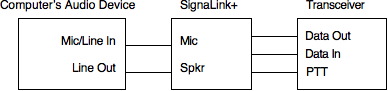
The SignaLink SL1+ takes the line output from the computer (or an D/A converter that is connected to the computer) and converts it to two signals: the first path feeds an audio output to modulate the transmitter (in the case of Yaesu, this is called “Data In”). The second path switches the PTT signaling pin through VOX circuitry that is in the SL1+.
In the opposite direction, it takes the audio output from the receiver (called “Data Out” by Yaesu) and feeds that to the line input of the computer (or an external A/D converter connected to the computer). Fig B.1 shows where the SignaLink is placed.
Notice that the audio output from the SignaLink is labeled “Mic” since it is intended to go into the microphone or line input of the computer’s audio device.
References
Baudot Codes: http://home.austin.rr.com/kinghome/signpage/baudot.html
Baudot Codes: http://www.arrl.org/notes/1832/ch30.pdf
Stereo jacks wiring: Stereo jacks