In a previous section, we have seen how you can set up the geometry (shape) property for a wire. In this section we will show how you can assign electrical properties, such as a voltage feed or a inductive load, to the wire.
Open the Element inspector as shown earlier. Notice that the top row or tab buttons include a tab for Excitation and another tab for Loading. You can create a feed point in a wire. You can add a load, such as a resistance of a flag antenna or an inductance of a trap antenna, to the wire.
You can also use the loading parameters to model a wire that has finite resistivity rather than a wire with infinite conductance.
Placing an Excitation on a Wire
The default excitation for a wire is None.
NEC-2 usually works with voltage sources. You can place a voltage source on a wire by selecting the Excitation tab and then selecting the Voltage Source tab. Be sure to leave the tab set to Voltage Source when you leave the Excitation panel.
If you want to remove a feed point, first select Excitation, and then select None.
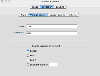
As shown above, you can specify the complex value of the voltage at the feed point. If you only have a single feed point, the value of the voltage is not important. Note that using 0.0 volts at a feed point is not, in general, the same as using None as the feed point.
You can place the feed point at various positions in the wire. Please note that if you choose Center, the number of segments (the number specified in the segments column of the spreadsheet) must be an odd number, otherwise there is no way for NEC-2 to place the source at the precise center of the wire. For this reason, many people prefer to always use an odd number of the number of segments when they model an antenna in NEC-2.
You can also choose to place the source of the excitation at either the first and last segment of the wire, or at an arbitrary segment in the wire. The Segment number field must be between 1 and the number of segments in the wire if you choose to place the sources away from the center or either of the two ends.
Adding Current Sources
Notice from the above figure that you can also choose to excite a wire with a current source instead of a voltage source.
If you are designing a phased array antenna, you might prefer to use a current source instead of a voltage source, since the beam pattern depends directly on the relative current phase angles and magnitudes.
NEC-2 does not directly support current sources. Because of this, cocoaNEC synthesizes a current source by first creating a companion small wire element for each current source. These added elements are translated far enough away from your other wires so that they have minimal effect on the "real" wires of the antenna. They are also specially tagged so that they are invisible in the geometry view of the Output window.
Instead of feeding your actual wire directly, cocoaNEC feeds the companion small wire instead, using a standard voltage source. cocoaNEC then creates a two-port network between this feed point and the segment that you have specified for the current source.
The admittance matrix of the two port network is made to look as if the wire at the second port is being fed with a known current that is proportional to the voltage at the first port. The two-port network also applies a 90 degree phase shift to the current-voltage relationship. For this reason, cocoaNEC also applies a 90 degree phase shift to the voltage source that applied to the companion wire.
Voltage sources appear as a single open circle in the geometry view of the Output window. Current sources appear as overlapping open circles (the standard pre-1970 symbol for current sources).
It is less complex to use the simpler voltage source. You only need to use current sources if you need to control relative current phases of multiple sources.
Placing a Load on a Wire
You can place a load on a segment of a wire in the same manner that you place an excitation. Note that it is perfectly OK to assign a source and a load to the same segment of a wire.
The following figure shows the interface for placing a complex impedance on a wire. You can place a single lumped impedance at the center of the wire, distribute the same impedance on all segments of the wire or distribute the impedance over a contiguous subset of segments of the wire.
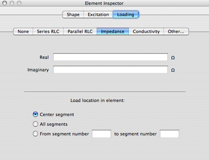
The loading property of a wire is defaulted to None.
In addition to an impedance, you can also place lumped series or parallel RLC circuits into segments of a wire, or specify a real conductivity value rather specifying impedance values.