The Networks sheet is opened by clicking on the Networks button of the spreadsheet window. Two-port networks allow you to connect two different wire elements together. A transmission line is a useful special case of a 2-port network.
As with other tables in cocoaNEC, click on the plus (or minus) buttons below the table to add (or remove) a two-port network or transmission line:
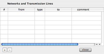
Figure 1 - Networks
Sheet
The plus button has a
contextual menu. If you hold down the right mouse button
(or use a control click) when the cursor is over the plus
button, you will see the contextual menu and you can select
whether to add a new transmission line or a new two port
network. The default, by left clicking on the plus button
selects the transmission line.
If you select a transmission line, '"TL" will appear in the
type column of the table. If you select a two port
network, "NT" will appear in that column.
The from and to fields are used to enter
names of two wires. The following figure shows a
spreadsheet interface:

Figure 2 -
Spreadsheet
Notice the spreadsheet column
on the right that has the "name" heading. We have earlier
said that this is an optional column. We will now show how
it can be used, other than just contain names to remind you
of what the wires are being used for.
One of the the names in Figure 2 is "shortElement" and the
other name is "longElement." These names can be arbitrary
strings, but they have to be unique. These are also the
names that you would use in the to and
from columns of the Networks table to identify the
wires you are connecting together. Like so:
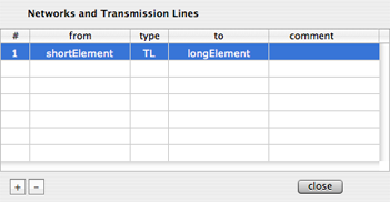
Figure 3 - To/From Wire
names for Networks
The comment field is for you to use as a note or a
reminder. cocoaNEC does not use it to hold any data it
needs.
The column below the # column is added automatically by
cocoaNEC. Just as in the spreadsheet, if you double click
on the number in this column, a Network Inspector window
will appear, allowing you to set the transmission line or
2-port network parameters.
Figure 4 shows the Network Inspector for a transmission
line element:
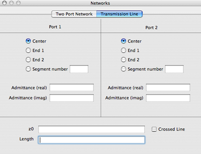
Figure 4 - Transmission
Line Inspector Panel
As you can see, just like with excitations and loads, the
ends of the transmission line can be placed at various
position along the wire. Furthermore, the transmission line
can be terminated at either end with a complex admittance.
If you don't want any termination, just leave the
admittance fields empty.
You can also specify the impedance of your line and the
electrical length of the line. You can apply a 180 degree
phase reversal to one end of the transmission like by
selecting the Crossed Line checkbox.
The following figure shows the Network Inspector for a
two-port network:
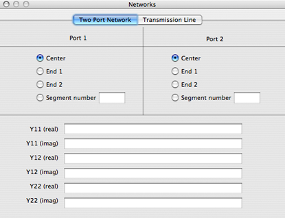
Figure 5 - Two Port
Network Inspector Panel
The network is defined by a
complex admittance matrix. It is assumed to be passive, so
the y21 term is identical to the y12 term.