The Environment sheet is opened by clicking on the Environment button in the spreadsheet window. This is where you set the frequency, ground parameters and ground radials for your antenna model.
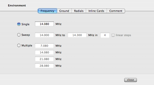
You can choose a single fixed frequency to analyze your antenna model, or apply a sweep between two frequency limits, or select up to four arbitrary frequencies.
If you choose a frequency sweep, you can specify the total number of frequency steps and you have the option to use linear frequency steps or geometric frequency steps.
You can also choose to use up to four arbitrary frequencies. This mode can be useful when you are modeling a multiband antennas where you would like to see the feed point impedances for all the bands on the same plot in the Output window. If you need fewer than four frequencies, you can leave the unused text fields empty.
Grounds
The Ground panel in the Environment sheet lets you set the relative dielectric constant and the conductivity of the ground under your antenna.
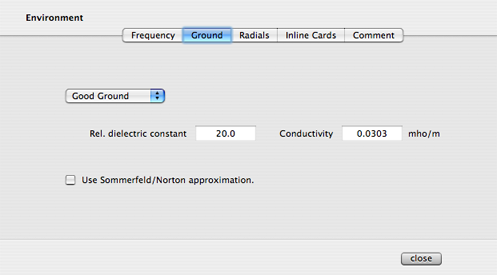
There are some preset "grounds" (i.e., relative dielectric constant - conductivity pairs of numbers) that are selectable with the pop up menu in the Ground panel.
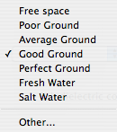
By picking Other... you can enter your own numbers.
You can use the more accurate Sommerfeld ground approximation by checking the Use Sommerfeld/Norton approximation checkbox.
Radials
The Radials panel allows you to include a ground screen under your antenna.
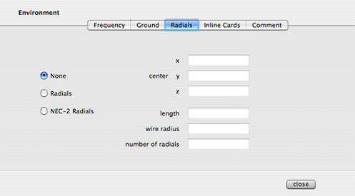
Selecting the None option will cause your antenna to be modeled in the absence of any radials. By selecting the Radials option, you can create a set of wires centered at (x,y,z) each one with the given length and with the given wire radius. The advantage of generating radials this way is that the wires are specially tagged so that the Output display can choose to draw them or not draw them.
Radials generated this way, however, are not suitable for use with ground mounted vertical antennas since NEC-2 does not allow wires to be close to ground.
To model ground mounted vertical antennas, you should use the NEC-2 Radials option. When you choose to use NEC-2 ground radials, the center of the radials must be placed at x=0, y=0 and z=0. Your ground mounted vertical antenna must therefore have one end at (0,0,0). NEC-2 radials are not drawn in the geometry view of the Output window.