micro KEYER Configuration
The microKeyer, microKeyer II, digiKeyer, digiKeyer II and CW Keyer can be configured by sending it a string of numbers. Often however, the bits that controls a single function (e.g., CW) are scattered among the configuration string as new features are incrementally added by microHAM. This makes the settings string moderately arcane to figure out.
µH Router attempts to make it less complicated to configure the keyer by presenting the settings as logically grouped GUI elements to the user, and then collecting the information into a properly formatted string that is sent to the keyer.
Main Settings Window (microKeyer, microKeyer II, digiKeyer and CW Keyer)
To open the Settings window, click on the Config button in the Preferences panel. The following is the default version of the settings window for all keyers except the digiKEYER II (see Figure 2 for the digiKEYER II):
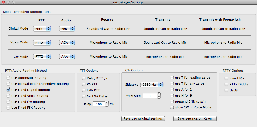
Figure 1: Settings window
for the microKeyer, microKeyer II, digiKeyer and CW Keyer
The current microHAM keyers
have either three or four routing modes. The microKeyer II
has a digital, voice and
CW modes. The old microKeyer and CW Keyer
have an additional FSK mode, whose PTT and Voice
functionality is merged with the Digital mode in µH Router.
Internal to a keyer are relays that route PTT and audio
signals. The routing can be set up to be a function of
which mode has been selected.
Main Settings Window (digiKeyer
II)
The digiKeyer II does not support
voice modes and the only routing it provides are for PTT
for digital modes and CW. There is also no audio routing in
the digiKeyer II. Figure 2 shows the settings window to
configure a digiKeyer II. Please note that the older
digiKeyer will open a window shown above in Figure 1.
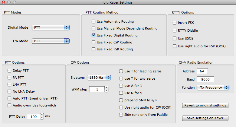
Figure 2: Settings window for the digiKeyer II
Audio Routing
Refering to Figure 1, microHAM classifies audio routing of
radio inputs into A, B, C and D connections:
A - microphone is routed to radio mic input
B - sound card line out is routed to radio line in
C - sound card line out is routed to radio mic in and
microphone is routed to sound card mic input
D - sound card line out is routed to radio line in and
microphone is routed to radio mic in.
For each mode, the routing can be independently chosen for
the three states that the keyer is in, viz i) receiving,
ii) transmitting or iii) transmitting using the
foot-switch. Each audio routing is therefore defined as a
triple such as BBD, ACA, etc.
The popup menus to select the audio routing are shown under
the Audio heading in the Mode Dependent Routing
Table box. There is one audio routing menu for each
mode.
Most routings do not make sense, and µH Router's menus only
show the "meaningful" routing in the microHAM
documentation. In addition, the ABCD nomenclature is
expanded into descriptive phases to the right of each popup
menu.
In the above figure, the Voice mode audio routing is set to
ACA. Note that the descriptive phrase under the Receive
column (i.e., for the first "A" of ACA) is displayed as
"Microphone to Radio Mic." When you are transmitting, the
routing will be "C" from ACA and the description under the
Transmit column is the corresponding "Soundcard Out to
Radio Mic."
When you select a different item in the Audio routing popup
menu, the descriptive phrase will change to reflect the
menu.
PTT Routing
Each mode has its own PTT routing. Following the
"meaningful" PTT routing in the microHAM documentation, the
digital mode popup menu allows you to key PTT1 or PTT2 or
both PTT simultaneously. Voice mode allows PTT1 and PTT2,
and CW mode allows PTT1, PTT2 or QSK. You can also select
None in any of the PTT menus.
Please note that with the cabling supplied by microHAM,
PTT1 is wired to the radio's microphone connector, and PTT2
is wired to the radio's accessory connector.
The digiKeyer II does not have separate PTT1/PTT2 paths.
There is only a single common PTT path.
Switching Modes
A microHAM keyer can be commanded to switch between
digital, voice (if supported by the keyer) and CW modes.
When it is switched to digital mode, the keyer will be
using the PTT and audio routing that is chosen above.
When "forced," the routing method will not change when you
switch modes. The PTT/Audio Routing Method box
near the bottom left of the Settings window lets you
determine if routing is switchable or "forced" to a fixed
mode.
You can "force" the keyer to use one of the three PTT/Audio
routings by selecting one of the Use Fixed Digital
Routing, Use Fixed Voice Routing, Use Fixed CW Routing or
Use Fixed FSK Routing checkboxes in the PTT/Audio
Routing Method box.
If you select Use Automatic Routing, the routing
method will change depending what you have selected on the
transceiver.
PTT Options
The microHAM keyers come with extra relays for driving
external PA and bypassing LNA or disabling the receive
antenna. To select them, use the checkboxes in the PTT
Option box. Normally, you will want to deselect them to
avoid extra relay clicking. In addition, you can apply a
PTT delay.
CW Options
The CW Options box has checkboxes for substituting cut
numbers for serial numbers that are generated by an
external PS/2 keyboard, and also a stepper to control the
step size when changing the speed (WPM) from the PS/2
keyboard. There is a popup menu for choosing the sidetone
frequency or turning it off. In the case of the microKeyer
II, this tone is output on the speaker driver.
As shown in Figure 2 above, the digiKeyer II include a tone
decoder for detecting on-off audio keyed tones (OOK) when
present in the right stereo channel of its sound card for
hard keying a CW transmitter.
RTTY Options
The RTTY Options box has a checkbox to select the FSK
Polarity, and checkboxes for selecting the options RTTY
options (Diddle and USOS) when FSK is keyed from an
external PS/2 keyboard.
As shown in Figure 2 above, the digiKeyer II include a tone
decoder for detecting on-off audio keyed tones (OOK) when
present in the right stereo channel of its sound card for
hard keying an FSK transmitter.
Save Settings on Keyer
When any parameters in the Settings
Window is changed, the change is immediately sent to the
keyer. The settings are also saved in the µH Router
preferences ("plist file") when you exit µH Router. The
next time µH Router is launched, your preferences are first
sent to the keyer.
When you quit µH Router, the keyer will eventually switch
to the default settings that are stored in an EEPROM in the
keyer. You can save your preferences to this EEPROM by
clicking the Save Settings on Keyer button. The
keyer will then remember your settings even if you power
the keyer off and back on.
Revert to original settings
The settings are reverted to "original"
state, if you are running µH Router the first time.
micro KEYER II Extensions
If you are connected to a microKeyer II, the microKeyer
Settings Window includes an extra button at the bottom left
of the window with the caption "microKeyer II extensions."
When you click on this you will bring up a window that has
the Extended settings which are available in the microKeyer
II.
LCD Display
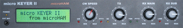
The microKeyer II includes a two line
alphanumeric LCD display in the front panel, each line
capable of displaying 16 characters.
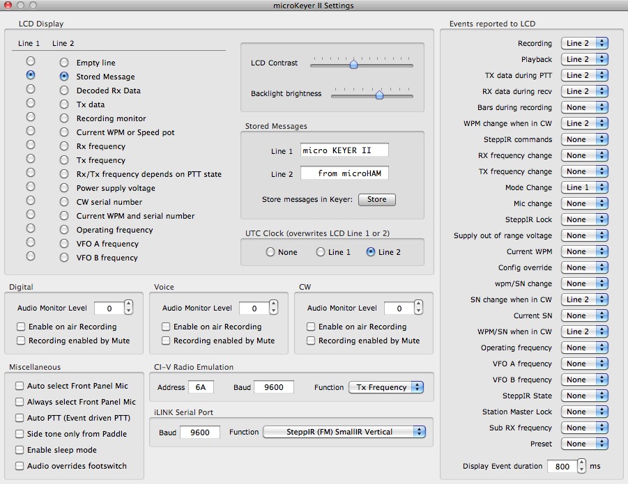
The LCD Display box at the upper left of the
Extensions panel controls the two-line LCD panel of the
microKeyer II.
The two columns of radio buttons on the left of the LCD
Display box allow you to choose what you would like to
display in each line of the LCD panel.
"Empty line" means just that, a blank line. "Stored
Message" are messages which are stored in the EEPROM or
temporarily sent from the computer. The following figure
shows the default (factory) message from a new micro KEYER
II:
Statically stored Messages
When µH Router is running, and if you had
selected the "Stored Messages" radio button for that LCD
line, either one or both of the two LCD lines are replaced
by the two text fields (Line 1 and Line 2) in the
Stored Messages box in the Extensions Window.
You can persistently write these messages into the EEPROM
inside the microKeyer II by using the Store button
in the Stored Messages box. The downloaded
messages will then remain in the keyer even if you power
cycle the keyer, and even when µH Router is not running.
Please note that Storing
messages on the Keyer is independent from storing the other
settings, which is done using the Save Settings on Keyer
paragraph above.
Instead of displaying the "Stored Messages", you can choose
among a number of status messages that are generated
internally by the microKeyer II.
For the example image below, the text field in Stored
Message Line 1 was set to "W7AY". The radio button for
LIne 1 is set to "Stored Message." The radio button for
Line 2 is set to "Current WPM and serial number."
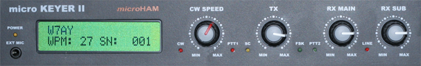
Notice that the WPM number changes when you change the CW
Speed knob.
The LCD display reverts to the EEPROM setting (including
the "stored messages") that is stored in the keyer a few
seconds after you quit µH Router.
On the right of the LCD Display box, you will see a box
with two sliders. The LCD Contrast slider allows
you to change the contrast of the LCD and the Backlight
brightness slider allows you to adjust the brightness
of the LCD background.
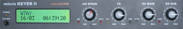
UTC Clock
Below the Stored Messages box is a UTC Clock box. This
allows you to overwrite the first or second line of the
display with the UTC date and time. If selected, µH Router
would generate a new UTC clock message every second and
send it to the keyer. The date-time information comes from
you computer clock, so be sure to correctly set both the
time and time zone of your computer in System Preferences.
The following image shows the UTC clock set to overwrite
the second line of the LCD display.
Please note that this is not a built in feature in the
microKeyer II. The clock is being driven by µH Router and
the clock will stop when you quit the router .
Events
The microKeyer II has a set of "events" that
can momentarily replace one of the two LCD lines. This is
controlled by the column of popup menus in the Events
Reported to LCD box on the right of the Extensions
Window.
You can select None, Line 1 or Line
2 in the popup menus. If None is selected,
the event will be ignored. If set to Line 1, the
event will be reported to top line of the LCD panel. If set
to Line 2, the even will be reported to the bottom
line of the LCD panel.
The duration an event stays on the LCD is set with the
Display Event Duration stepper that is near the
bottom center of the Extensions Window.
Audio Monitor/Recording
A set of three boxes (for Digital, Voice and
CW modes) contains the controls for selecting the monitor
level and audio recording.
Miscellaneous Checkboxes
There is a collection of miscellaneous
checkboxes at the bottom left of the Extensions window. Two
of them controls the behavior of the front panel EXT MIC
jack.
Auto PTT is basically a VOX driven PTT. This
function can be used for voice modes and also for digital
modes that have full duty cycle (e.g., RTTY or MFSK16) or
close to full duty cycle (e.g., PSK31) to keep the VOX
activated. With those modes, you will not need to use hard
keyed PTT from the software.
Enable sleep mode enables the keyer to sleep when
the computer and the radio are both disconnected or
switched off.
The Audio overrides footswitch checkbox enables
audio from the sound card to switch the keyer from using
the sound card instead of from the microphone even if the
foot switch is depressed.
The Side tone only from Paddle checkbox causes
side tone to be generated only when the keyer is operated
from a paddle.