Keyer Protocol
(For details of the microHAM Keyer Protocol, please contact microHAM.)
A microHAM keyer communicates with the computer through a USB connection. The USB connection emulates a 230,000 baud full duplex serial port with an FTDI chipset.
In the case of the DIGI KEYER, there is an on-board two port USB hub - one port of the hub is connected to the above FTDI serial port and the other port is connected to the audio codecs. The codecs in the DIGI KEYER are completely distinct and separate from the Keyer Protocol . The codecs do not go through the router, but are connected to the operating system through the CoreAudio interface. The router only deals with the serial port side of the DIGI KEYER.
(NOTE: you can see the USB hierarchy in the System Profiler (/Applications/Utilities/System Profiler) under Hardware > USB.)
The serial stream of the Keyer Protocol is sent in four-byte data frames. The most significant bit of each byte in the frame is used to provide the frame sync.
Each four-byte data frame is multiplexed into three data channels.
The header byte of a frame contains various sync and data bits. The remaining three bytes of a frame contains data for each of three channels of information.
The first data channel contains the data for the radio's CAT port, a second channel contains the data for a second radio's CAT port, and a third channel is a channel that is further demultiplexed for use by lower rate data for flags, control, WinKey, FSK, etc).
![]()
The header byte of a frame also
contains three bits which act as mask bits (called the
validity bit in the Keyer Protocol documentation) for the
three data channels. If a particular mask bit is not set,
the data channel that corresponds to that mask bit is
considered to be empty.
Frames
The four-byte frames are collected in the
Keyer component of the µH Router.
The start of each frame of four data bytes is found
inspecting the msb of each of the four data bytes (see
above). To accomplish the frame sync mechanism, only 7 bits
of data are transmitted in the three data channels; the msb
of those bytes are always set while the msb of the header
byte is always cleared. The actual msb data bits of the
three data channels are contained in the body of the header
byte.
When a properly formed frame is found, the Keyer component
sends the frame on to the Router component.
Blocks and the sequence of frames in a
block
Data is sent in blocks that is made up of the frames
mentioned in the previous paragraph. Each block of data
contains between one and five frames. The beginning of a
block is identified by yet another bit in the header byte
of the frame.
The shared data (last byte) of a frame contains different
information depending on the sequence position of the frame
within a block. The shared data can represent a byte
containing flag bits (PTT, foot switch, etc), a Control
byte, a Winkey character, an FSK character, etc.
The shared channel in the first frame of a block is
interpreted as a byte containing flag bits. The
shared channel in the second frame of a block is
interpreted as Control data, the shared channel in
the third frame of a block is interpreted as
WinKey data, the shared channel for the fourth
frame of a block is interpreted as FSK data and
the shared channel for the fifth frame of a block is
interpreted as data for a second FSK channel (not
available in currently microHAM keyers).
The following figure shows the structure of a block with
all five frames.
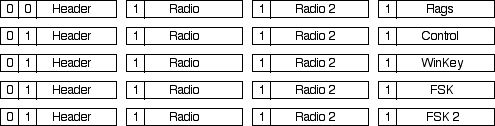
To send a single flag byte, a
block with a single frame is sent, with the flag byte in
the shared channel position in the frame.
To send a control byte, a block that contains two frames of
data is sent, with a control byte in the shared channel
position of the second frame. If a flag byte is also sent,
the flag byte is sent in the shared data position of the
first frame of the block. If the bits in the flag byte need
not be updated, the mask bit in the first frame's header
that belongs to the shared channel is not set.
To send a Winkey byte, a block of three frames is sent ,
etc.
The flags channel is itself further
shared by individual bits that sets the RTS state of the
Radio channel, the PTT keying state, and a serial line for
CW keying. The devices sends back the state of the Radio
channels CTS line, the state of any connected foot switch
and the state of the squelch (only available in the DIGI
KEYER) through the "flags" channel.
The control channel is used to set up
either temporary or persistent (EEPROM) configurations in
the keyer. These configurations include the CAT serial port
parameter (baud rate, data size, etc) the FSK parameters
(baud rate, data size, etc) and Winkey message buffers. In
addition, the control channel is also used for downloading
new firmware and requesting keyer version numbers.
The WinKey channel is connected to the
onboard K1EL WinKey chip (note: the DIGI KEYER
does not come with a WinKey chip) and allows
perfect Morse timing from multiprocessing operating
systems such as Mac OS X and Windows.
The FSK channel is connected to a UART
that can be configured as a slow speed serial port that can
operate using 5 to 8 bits of data.
(NOTE: the
FSK ports in the microHAM devices do not work at the
nominal Amateur RTTY data rate of 45.45 baud -- you will
have to configure it to use 45.0 baud. While this is not
ideal with demodulators that are tuned for 22 msec bit
periods, there should be no noticeable difference in
performance except when the SNR is very poor.)