Preparations
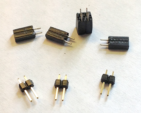
Before you start, first prepare the 3M Boardmount headers and sockets by cutting them from the longer pieces.
Header pins (J22, J23 and J24) are used to configure the daughter card, and cutting them is moderately straightforward. Just use a box-cutter blade to chisel the required 2-pin pieces at the scored marks between each pin the longer header strip.
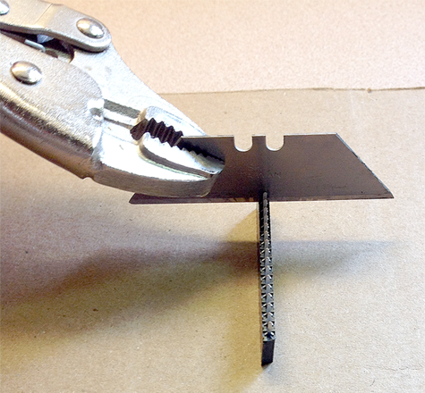
The female interconnecting sockets (P20, P22, P23 and P24) that go between the daughter card and Hermes are a little trickier. The method I choose requires sacrificing a pin (a row of two pins in the case of the two-row socket for P20) since cutting precisely between the pins is very difficult.
Place the box-cutter blade that is held by a Vice-Grip right against the pin that is to be sacrificed, and give the blade a smart whack with a hammer. Dispose of the sacrificed pin, and file away any excess plastic. Do not file too much, since that will weaken the pins that you are actually using. The only sockets that need to be closely filed are P23 and P24, which are next to one another.
Be sure to use eye protection.
Put the processed connectors
aside. You won't need them until the final steps of
construction.
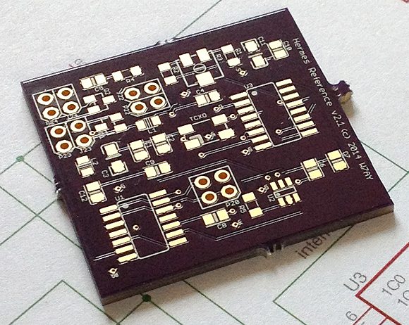
If you had purchased your board
from OSH Park, it will come with little
tabs of various sizes along the boarders of the board.
These are the locations where your board is attached to
other customers' boards on the larger panel. You will
need to cut and file them away. The ground planes are
inset from physical border of the board, so you are
pretty safe while filing.
Before soldering the components
and occasionally while working, check for Power-Ground
shorts, specifically between pins 7 and 14 of U1 and also
between the two pins of P23. If any shorts develop during
soldering, it will be easier to identify where the problem
occurred.
Components
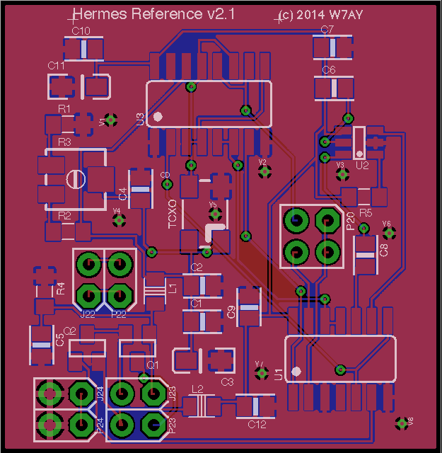
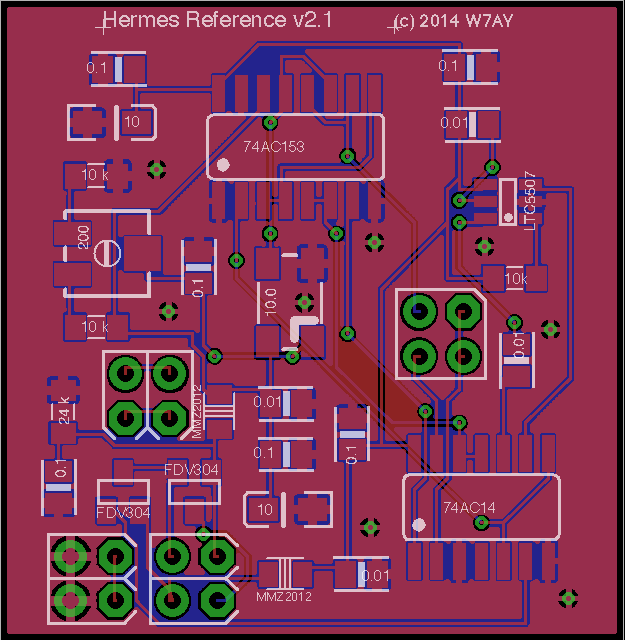
The following shows the component placement:
The following shows the component values:
Soldering the Components
Except for the tantalum capacitors, all of the 2-pin resistors, capacitors and ferrite beads have the 0805 surface mount dimension. These are moderately easy to manually solder (I use a heat gun myself). All parts (except for the connectors, which are through-hole parts) are on the top surface of the board.
For manually soldering, I have found that it is easiest to first solder the multi-pin chips, starting with the LTC5507 (which has 0.95 mm pin centers). After that, solder in the resistors, capacitors and ferrite beads, followed by the TCXO and then the trimpot, and leaving the through-hole connectors for last.
Use Kapton tape and kitchen aluminum foil when necessary to protect already soldered components.
You may have your own preference of the order to solder parts. In my case, I used the following order:
- LTC-5507 at
location U2.
- 74AC14 at
location U1.
- 74AC153 at
location U3.
- FDV304P
MOSFET at locations Q1 and Q2.
- 0.1 µF
capacitor at locations C1, C4, C5, C7, C9, C10.
- 0.01 µF
capacitor at locations C2, C6, C8, C12.
- Ferrite bead
MMZ2012R601 at locations L1 and L2.
- 10 kΩ
resistor at locations R1, R2 and R5.
- 24 kΩ
resistor at location R4.
- 10 MHz TCXO.
- 10 µF
tantalum capacitor (be sure to obey polarity) at
locations C3 and C11.
- 200 Ω trimpot
at location R3.
- connectors
P20, P22, P23, P24 (see next section).
- configuration
headers J22, J23 and J24.
Soldering the Interconnecting Sockets and Headers
Start with the sockets that go between Hermes and the daughter card.
I have found that the easiest way to maintain alignment is to use Hermes itself as a template. Use the usual ESD precautions and a grounded soldering iron for this step.
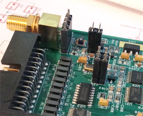
First, insert the sockets (P20, P22, P23 and P24) into the Hermes headers that are marked J20, J22, J23 and J24:
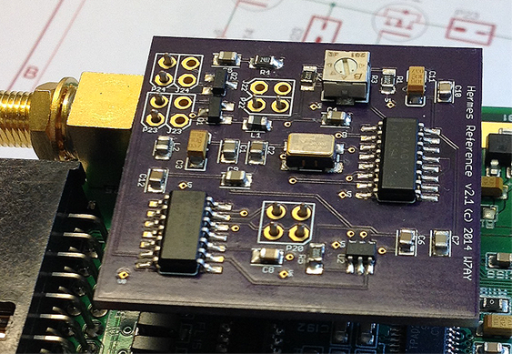
Insert the connector pins (P20,
P22, P23 and P24) through their holes on the daughter card,
as shown below, and solder them while applying a slight
pressure on the daughter board.
The Jumper headers at the top
of the daughter card are next soldered from the
bottom. The finished board is shown
here.