K3 Backend IMD
Kok Chen, W7AY
[w7ay (at) arrl (dot) net]
December 15, 2010
The following measurements were made (December 15 2010) on an Elecraft K3 (S/N 01432).
It is an attempt to measure the intermodulation distortion (IMD) of the K3 receiver when there are more than one signal coming through the roofing filter.
The RF input for the K3 consists of two of the four DDS oscillators in a Novatech 409A RF signal generator. The signal generator outputs are combined in a resistive combiner that has 20 dB of attenuation between the signal generator ports and the RF output to the K3, providing about 40 dB of isolation between the two generator outputs.
The K3 Headphones output is sent to a E-MU 0404 sound card.
The following image shows the
physical setup:
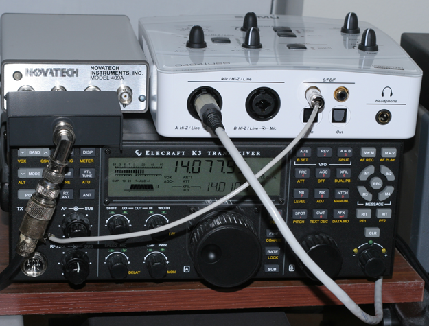
The small gray box in front of the Novatech generator
contains the resistive combiner. The combiner was designed
to look like two pi-attenuators that share a common output
resistor. The resistors are computed to give 50 ohms
impedance at each port when the other two ports are
terminated by 50 ohms, and to give 20 dB attenuation
between the output port and one of the two input ports when
the other input port is terminated.
The 1/4" TRS plug from the E-MU goes to the 3.5mm
Headphones jack at the rear of the K3. The cable consists
of one twisted pair from a CAT-5 UTP cable. The E-MU is
wired for balanced input (the Tip and Ring at the E-MU end
are connected the tip and sleeve of the Headphones
connector of the K3). The wire that is connected to the
E-MU's S/PDIF connector is just a ground wire; the sleeve
of the E-MU's TRS connector is left open. The end of the
ground wire that is hidden by the PL-259 connector holds an
alligator clip which clips to the ground of the front panel
Phones jack.
The AGC of the K3 is turned off and the RF attenuator of
the K3 is turned on.
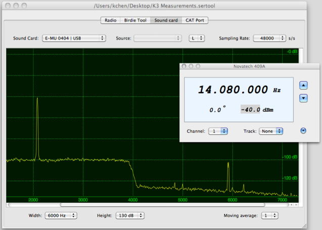
Signal analysis is performed in Mac OS X, with a pair of
home brew programs to plot the spectrum, and to control the
Novatech signal generator (one of the things you have to be
prepared to do when you own a Macintosh is to write a lot
of your own programs :-). The Mac OS X screen looks like
this:
The following shows a
"reference" spectrum capture:
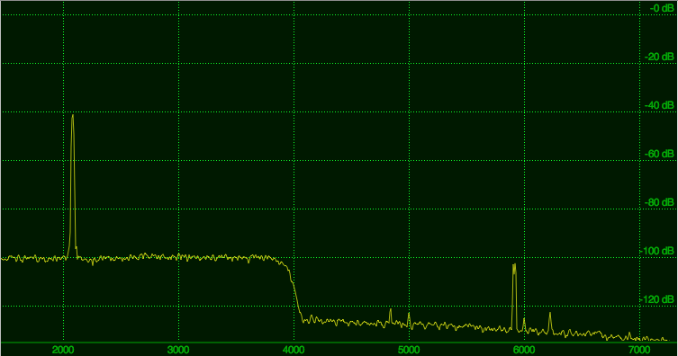
Figure 1. "Reference" spectrum
In the above, the K3 is tuned
to 14077.95 kHz, and the signal generator is set to output
14080.00 kHz. The hi cut of the DSP filter is set to 4 kHz
(the roofing filter in this case is a standard 6 kHz filter
from Elecraft). The Novatech generator is set to put out
-40 dBm.
Throughout this document, the sound card gain is fixed so
that the noise floor of the K3 headphones lines up with the
"-100 dB" position in the spectrum plots. The noise to the
right of 4000 Hz in Figure 1 is the noise floor of the E-MU
itself. (Strictly speaking, the noise floor on the left is
the noise floor of the K3 plus the noise floor of
the sound card.)
I find that a good estimate of the actual signal generator
level at the Antenna connector of the K3 is obtained by
using Rob Sherwood's measurement of the
K3's noise floor of about -130 dBm. In the above case,
the signal is 60 dB above the noise floor, so it is
about -70 dBm (or just a little stronger than an S9
signal).
The signal near 6000 Hz is unidentified, but rises and
falls together with the carrier level. It is not an audio
harmonic of the carrier tone (as we will see later) and
appears to be a composite of two very close in carriers
(you can just about resolve them in Figure 1).
This is what the spectrum looks like when the signal
generator output is increased by 30 dB:
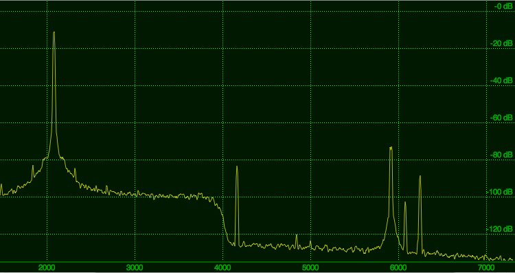
Figure 2 Audio harmonic distortion from the K3
headphones output.
Both the second harmonic and
third harmonics of the audio tone can be clearly
identified in Figure 2: the second harmonic is the large
signal that is a little higher than 4000 Hz(about -75 dBc)
and the third harmonic is the strong signal that is a
little higher than 6000 Hz (about -80 dBc).
The Novatech's phase noise is also very apparent in Figure
2. The phase noise of the Novatech is spec'ed at -120 dBc
at 10 kHz, but it has not been a problem when used in this
context.
The next figure shows the spectrum when a second carrier at
14080.70 kHz is added at the resistive combiner.
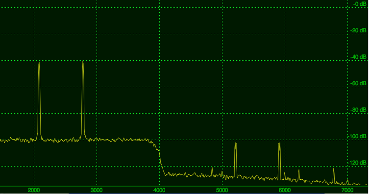
Figure 3 Two-tone signal at 60 dB above noise floor
There are now more spurious signals above 5000 Hz. However,
with both carrier levels set at 60 dB above the noise
floor, no IMD is apparent, so the noise limited IMD value
is also -60 dBc.
In Figure 4, the two carriers are both raised to 70 dB
above the K3 noise floor.
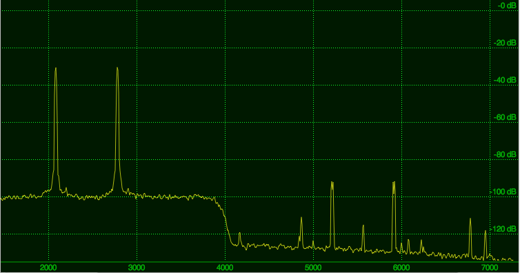
Figure 4. Two-tone signal at 70 dB above noise floor
There is still no evidence of
any IMD above the noise floor in Figure 4, so for two
carriers that are 70 dB above the noise floor, the IMD is
noise limited and now improved to about -70 dBc.
In the next figure, the carrier levels are raised yet
another 10 dB to 80 dB above the noise floor.
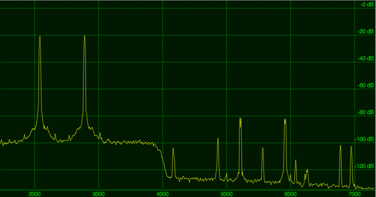
Figure 5. Two-tone signal at 80 dB above noise floor
The phase noise from the
Novatech is now very evident, but should not present a
problem where the IMD would have been located at.
Still, no IMD is visible above the noise floor. The noise
limited IMD is now -80 dBc. At this point, the two signals
should correspond to about S9+23 dB.
The next figure shows signals that are 85 dB above the
noise floor (the largest signals before the IMD becomes
visible above the noise floor):
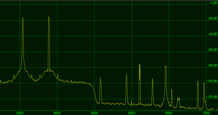
Figure 6. Two-tone signal at 85 dB above noise floor
The IMD is still noise
limited, now at -85 dBc.
Finally, with the signal levels at 90 dB above the noise
floor, we see IMD in Figure 7.
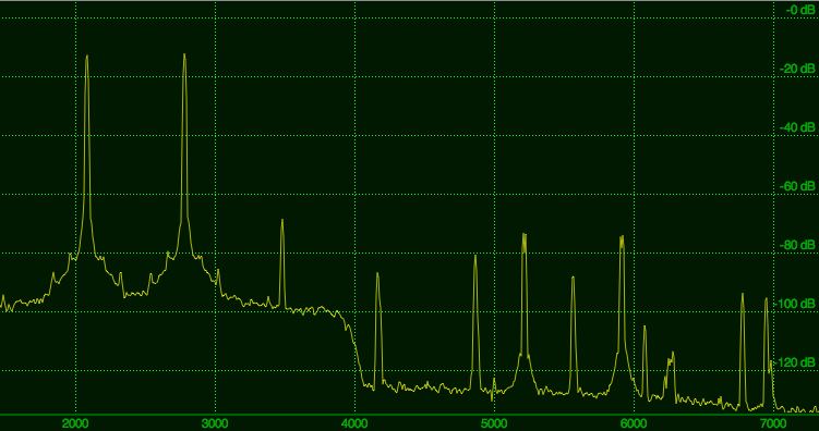
Figure 7. Two-tone signal at 90 dB above noise floor
A large IM product finally appears at about 3500 Hz in the
spectrum, at about -56 dBc.
The two signals are now about S9 + 33 dB (assuming Rob
Sherwood's -130 dBm number for the noise floor).
In the following figure, the DSP filter's high cut is
lowered to 3.2 kHz:
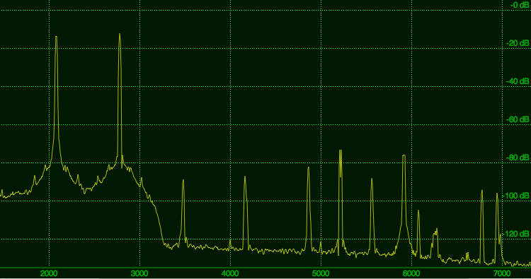
Figure 8. Two-tone signal at 90 dB above noise floor,
DSP filter at 3200 Hz
This places the 3rd order IMD
above the DSP filter cutoff. Any remaining IM product that
we see in Figure 8 will now have to be generated by the DSP
code, the D/A converter or the analog audio hardware. Any
IM product that was generated by the I.F. amplifier, the
second mixer or the D/A converter would have been filtered
away by the DSP filter.
Notice that the 3rd order IM product at about 3500 Hz has
dropped to less than -75 dBc, from the -56 dBc in Figure 7.
This implies that the -56 dBc IM figure in Figure 7 has to
come from the stages before the DSP filter (for example,
the I.F. Amplifier, second mixer, A/D converter or any soft
limiting in DSP).
Finally, for a sanity check, the next Figure shows the
output with one signal at about 90 dB above the noise floor
and the second signal at about 70 dB above the noise floor.
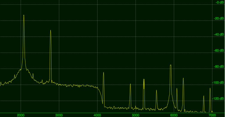
Figure 9. Two-tone signal at 90 dB and 70 dB above the
noise floor
Notice that there is no visible
IM product above the K3's noise floor.
Line Output of the K3
The spectra in Figure 1 through Figure 9 were recorded
through the Headphones output of the K3 because the IMD
from Line Output is extremely poor. This particular K3 has
been modified with 47 ohm resistors in parallel with
R19/R20 (a modification due to K8ZOA that was subsequently
published as an official mod by Elecraft). My earlier
measurements showed that there was a very large improvement
in IMD after the modification was made.
Using the Line Output, and with controls of the E-MU sound
card adjusted so that the noise floor of the Line Output
matches the Headphones output in Figure 1, the following
are seen. The gain of the Line Output in the K3 Config menu
is set to 011.
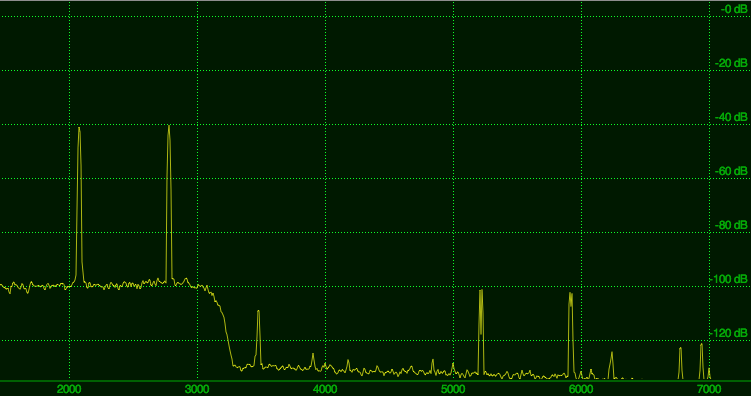
Figure 10 Two-tone signal at 60 dB above the noise floor
at K3's Line Output
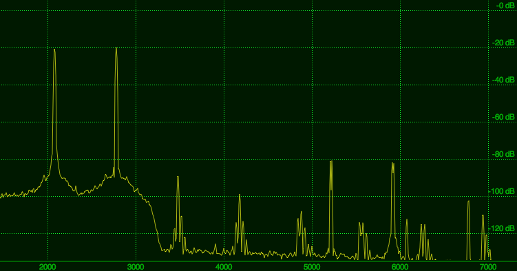
Figure 11 Two-tone signal at 80 dB above the noise floor
at K3's Line Output
Comparing Figure 11 with Figure
5, we see that for a signal that is 80 dB above the noise
floor, the headphones output was giving a noise limited IMD
of -80 dBc, while the IM product at the Line Output is
showing about -68 dBc (the IM product is close to 3500 Hz).
When the carrier levels are increase to more than 80 dB
above the noise floor (Figures 12 and 13 below), the K3
Line Output becomes practically useless:
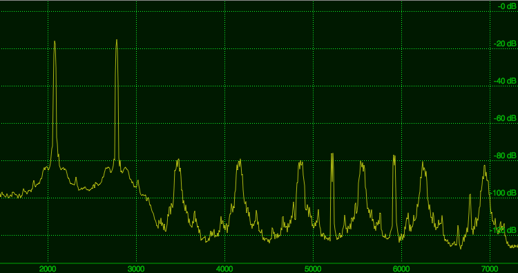
Figure 12 Two-tone signal at 85 dB above the noise floor
at K3's Line Output
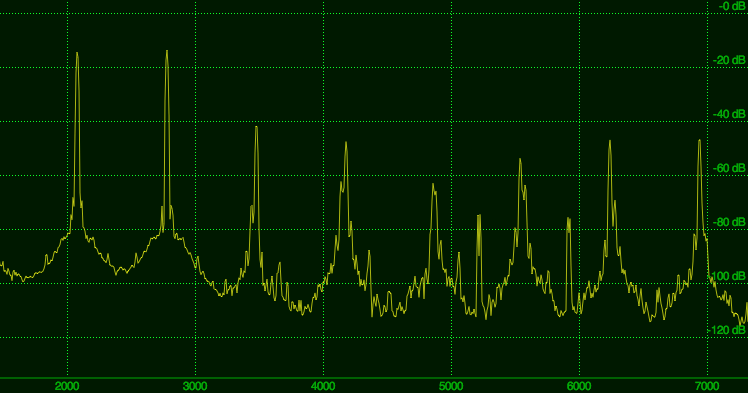
Figure 13 Two-tone signal at 90 dB above the noise floor
at K3's Line Output
Notice that the mess in Figures
12 and 13 is not cause by the Sound Card clipping (we are
well under that) since Figure 9 does not show anything like
Figures 12 and 13.
Observations
The K3's Headphones Output appears to be
free of IMD (the IM product is below the noise floor) even
when there are two carriers inside the roofing filter, with
each carrier 85 dB above the noise floor. I.e., there is
somewhere about 85 dB 3rd order IM dynamic range.
When the signal is over 85 dB stronger than the noise
floor, the IM from the headphones output appears to be be
coming from stages before the DSP filter (e.g., the I.F.
amplifier, second mixer, etc).
A single signal that is 90 dB above the noise floor,
together with a second signal that is 70 dB does not
present a problem (i.e., noise limited IMD even when only
one of the signals is 90 dB above the noise floor).
The K3 Line Output's IM dynamic range,
however, appears to be no better than about 70 dB. (Before
the K8ZOA Line Output modifications, the IMD number was
much worse.)
If you use wide band techniques (e.g., waterfall tuning for
PSK31 or RTTY), it might be worthwhile using the headphones
output instead of the Line Level output. Or modify the K3
line output to completely bypass the output transformers,
or replace the transformers in the KIO3 by higher quality
transformers.
The headphones output is not transformer coupled however,
and you will need to take the usual precautions to avoid AC
line noise, etc. In the above experiments, I have used the
balanced input at the sound card, with the grounds of the
sound card separately routed to the ground of the K3 using
a low impedance path. I had no difficulty in reducing the
AC hum to below the noise floor of the K3 receiver.
Whether you use the Headphones output or the Line Out
signal, keep the signal levels in check. If you operate
using a waterfall, try to keep the loudest carriers from
exceeding 85 dB above the noise floor if you are using the
headphones output, and keep strong signals well below 70 dB
above the noise floor when you use the K3's Line Output.