PSK31 and RTTY
Transmit Purity
Kok Chen, W7AY
[w7ay (at) arrl (dot) net]
The following measurements were made (January 2010) with a K3 (S/N 01432) runing MCU Firmware 3.68.
The K3 RF ouput is routed through a Directional Coupler (Elecraft CP1) into a 50 ohm dummy load. The -30 dB tap is passed through a step attenuator (Elecraft AT1) to the antenna input of a Yaesu FT-1000MP.
Recording
The audio output from the FT-1000MP is sampled with the sound card in the microKeyer II and sent to a Macintosh running cocoaModem 2.0, where IMD and spectral measurements are recorded. The EDSP and the RF Preamp of the FT-1000MP are turned off so as not to influence the IMD numbers. Sufficient attenuation is applied to the RF input of the FT-1000MP so as not to exceed an S4 on its meter (S5 is the point where IMD has been observed to start rising slowly). The bandwidth of the FT-1000MP is set to 2.4 kHz.
PSK31 IMD readings are from the values that are reported by cocoaModem (a long term spectral moving average) and also confirmed by "eyeballing" in the spectrum display to be sure the numbers reported by cocoaModem are not off.
Transmission
For AFSK measurements, the audio output from a second Macintosh, running another copy of cocoaModem 2.0 is sent through an M-Audio Transit sound card through the audio Line Input of the KIO3.
The audio level from the M-Audio Transit to the KIO3 is measured on a Fluke 76 multimeter. The PSK31 measurement is a little tricky to report since there are two crest factors involved, the crest factor of the sine wave PSK31 carrier composed with the envelope shaping of a PSK31 signal (a double sideband sinusoidal envelope at 31.25 Hz, when the PSK31 signal is sending the Idle Varicode).
For reference purposes, with an audio output level setting in cocoaModem that registerd 448 mV RMS with a PSK31 Idle signal, the corresponding RTTY Mark tone in the configuration panel (constant envelope factor) read 567 mV RMS on the same meter, and read 0.85 volt peak on a Tektronix TDS 2024B oscilloscpe. When unloaded (the M-Audio Transit not plugged into KIO3) the same settings registed 610 mV RMS on the meter; this last number will depend on the output impedance of the sound card.
The K3 Mic Gain was set to 6 and the VOX Gain is set sufficiently high (060) so that the transmitter is engaged for the different audio levels.
PSK31 - PSK-D Mode
The PSK-D IMD is measured by simply placing the K3 into manual transmission in with PSK-D and allowing the internal generator of the K3 to modulate the transmitter with the Idle Varicode.
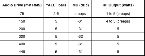
With the K3's PA turned off, the following are the PSK31 3rd order IMD values for different power levels:
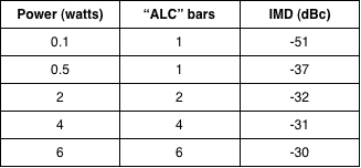
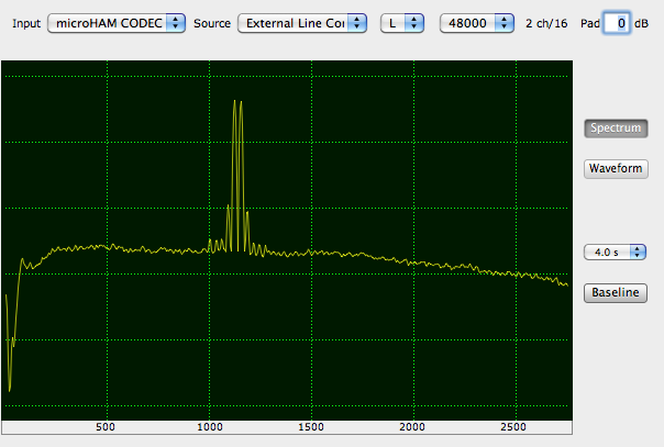
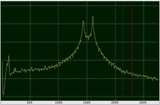
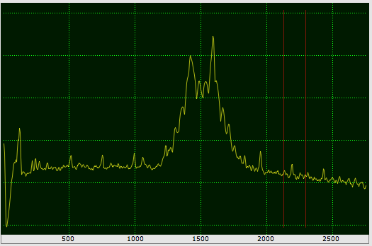
The 2 watt PSK-D spectrum looks like the following figure
in cocoaModem's config panel. Notice that a 4 second moving
average has been applied to each FFT bin. Notice that the
5th and 7th order IMD are very low. The predominat
distortion is the 3rd order IMD (which is what cocoaModem
measures). The horizontal green dotted lines are separated
by 20 dB.
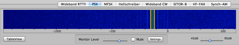
Just a hint of the IMD shows in cocoaModem's waterfall. The
IMD "rails" will not be noticable with lower SNR, of
course.
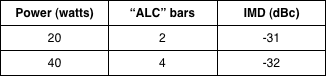
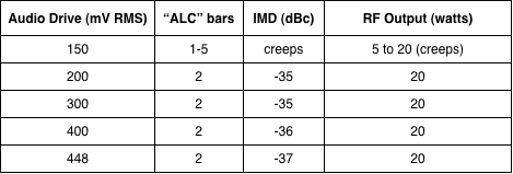
With the K3's PA turned on, the measured PSK31 3rd order
IMD are:
PSK31 - Data-A Mode
The PSK-A IMD under various RF Power setting and various
audio drive is measured by using the audio PSK31 signal
that is generated by cocoaModem.
5 watts
20 watts
50 watts
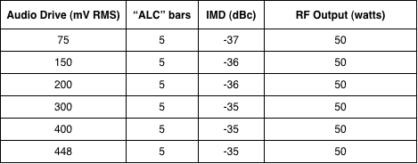
With the Mic Gain set to 6, audio drive under 150 mV for 5
watt RF power output and under 200 mV for 20 watt RF output
resulted in ALC reading, measured IMD and RF output all
"creeping." An audio level of between 250 mV and 350 mV
(and Mic Gain set to 6) produces stable output for all
power levels tested.
Notice too that the 20 watt and 50 watt outputs show clean
IMD readings, cleaner than the PSK-D mode (K3 internal
generator) by 3 dB to 5 dB. In fact, Data A is clener than
PSK-D at all power levels that were measured. This will of
course depend on how clean the audio generated PSK31 signal
is to start with (cocoaModem's audio IMD was measured to
exceed -80 dBc).
RTTY - FSK-D Mode
The following is a spectrum of RTTY diddles from an FSK-D
signal of the K3. RF Power was at 50 watts. A Morse paddle
is use to occassionally send an 'E' to keep the RTTY
Diddles alive. Again, he horizontal green dotted lines are
separated by 20 dB.
RTTY - Data-A Mode
The following is a spectrum of RTTY diddles from the Data-A
signal from the K3. The Audio FSK signal is generate by an
idling (diddles only) transmission from cocoaModem.
cocoaModem uses a Blackman window to waveshape the AFSK
output. When the transmitter's IMD is low, this produces
significantly narrower RTTY spectrum than a typical FSK
spectrum, as can be seen below.
The cocoaModem waveshaping results in an envelope that does
not have perfectly constant power. One result from the
waveshaping is a very low level overlap of the Mark and
Space signal. With transmitters that are not properly
adjusted or that have poor IMD, these Mark/Space overlaps
shows up as IMD byproducts. As seen in the figure below,
the K3 has a clean enough IMD to take advantage of this
envelope waveshaping. The IMD spurs are well below -55 dBc.
As seen here, like the PSK31 case, an RTTY signal that is
generated by Data-A mode is again potentially cleaner than
one that is internally generated by the K3 in FSK-D mode,
assuming the software modem has done some reasonable
filtering or envelope waveshaping (not all modems do this).