
cocoaPath User's Manual
version 0.30
Kok Chen
W7AY [w7ay
(at) arrl . net], Russ Carpenter AA7QU
[russ (at) natworld
. com]
Last updated: September 26, 2008
1 Introduction
cocoaPath is an HF Channel
Simulator, used primarily for testing new modem algorithms
and setting demodulator parameters. cocoaPath consists of
an input channel, an output channel, and an ionospheric
propagation model to connect the input to the output.
An audio signal is created by the input section of
cocoaPath. The input signal can come from a sound card, a
collection of built-in signal generators (PSK31, RTTY, CW
or steady carriers), or an AIFF or WAV format audio file.
The audio output from cocoaPath can be sent to a sound
card. It can also be written to an AIFF or WAV file. A
propagation model, for example to simulate propagation
conditions of high latitude flutter, is applied to the
input signal, and passed on to the output section.
The propagation models are based on the seminal 1970 paper
"Experimental Confirmation of an HF
Channel Model" by Watterson, Juroshek and Bensema.
Technical and implementation details of cocoaPath can be
found in the page that is linked by the Technical tab button above.
Propagation models that are defined by the CCIR 520-2 Recommendation (1992) and
the ITU-R F.1487 Recommendation (2000)
are included in the set of built-in models in cocoaPath.
A user can also create other propagation conditions that
are based upon the Watterson parameters.
2 System
Requirements
cocoaPath requires either Intel or PowerPC
Macintosh computers that run Mac OS X 10.5 (Leopard) or
newer.
3 User
Interface
When cocoaPath is launched, you will see the
main cocoaPath window shown in the figure below:
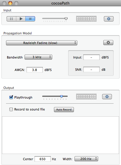
The cocoaPath window is
separated into three primary sections, Input, Propagation
Model and Output.
3.1 Input
Interface
The figure below shows the input section in
greater detail
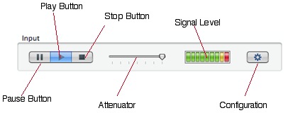
On the left of the input
section is a segmented control with Pause, Play and Stop
buttons to control an internal sound generator, an audio
(AIFF or WAV) file, or an input sound card.
The Pause button only works with input sound files. If Play
is pressed while the input section is paused, the file will
resume playing from where it was paused. If Stop is
pressed, play will stop, and the input file pointer will
point to the beginning of the audio file. If Stop is
pressed while the input is paused, the file pointer is
placed at the beginning of the audio file.
With internal sound generators and sound card inputs, the
Pause button behaves just like the Stop button.
An attenuation slider is immediately to the right of the
Stop button. The attenuator is only active if the sound
card input is selected. The slider is grayed out for other
input types.
The Signal Level measures the peak level of the input
signal every 32 ms. The red segment is lit if the signal is
within 0.5 dB of full scale. The yellow segment is lit if
the signal is within 1 dB of full scale. Each green segment
represents 3 dB of signal level change.
When toggled, the Configuration Button opens and closes the
input configuration panel. You can also close an opened
configuration panel by using the red "close window" button
at the top left of the window.
3.1.1 Input
Configuration
The input configuration panel controls the
source that is selected to provide the audio stream. When
the Configuration button is pressed, you will see a window
with the title "Input" as shown in the following
figure:
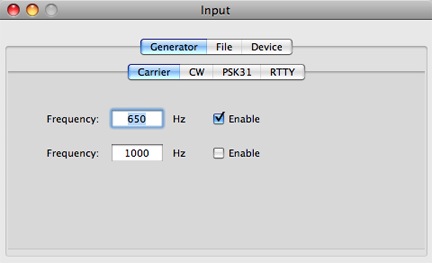
The upper row of tab buttons
selects the type of input to use as the input to the
simulator.
You can choose among certain internal signal generators,
AIFF or WAV audio files or sound card devices. The above
figure shows the panel's appearance when a built in signal
generator is selected.
In the above figure, the inner tab view chooses the
modulation mode of the signal generator. You can choose
between a steady Carrier, a CW (Morse) signal, a PSK31
signal, or a 45.45 baud RTTY signal.
As seen above, you can enable up to two carriers for the
steady carrier generator, and you can set the frequency of
both carrier.
You will see the next figure when the CW signal generator
is selected.
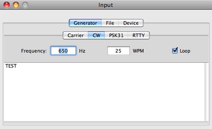
You can choose the CW
frequency, and the Morse speed in words per minute. The
text in the text view will be sent. If the Loop
checkbox is set, the text will be repeated until the
checkbox is cleared.
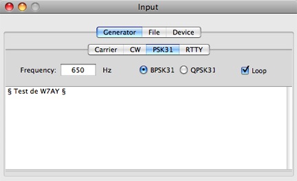
The PSK31 signal generator is shown below. Like the CW
generator, the center frequency can be chosen, and the text
can be repeated by setting the Loop checkbox. In
addition, each "section" symbol ( § or Option-6 on a
Macintosh keyboard) in the text will generate a short idle
Varicode. Longer idle patterns can be generated by using a
string of § characters. You can choose either BPSK31 or
QPSK31 modulation.
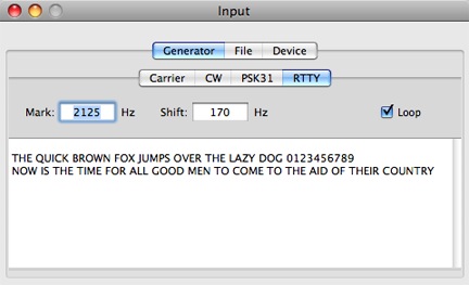
The RTTY signal generator is
shown below. You can "invert" (swap the Mark and Space
tones) the RTTY signal by using a negative "shift"
value.
3.2 Output Interface
The figure below shows the output section in
greater detail:
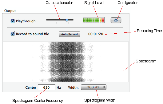
The width of the spectrogram can be chosen from 400 Hz down
to 12.5 Hz. Since it is very narrow, it is crucial that you
place the center frequency at or close to the input
signal's frequency or frequencies. The left of the
spectrogram is higher in frequency and the bottom of the
spectrogram has the most recent slice of the spectrum.
The Playthrough checkbox enables the simulator's
output to play on the sound card that is selected in the
output configuration panel (see below). If you select the
system sound output, you will be able to monitor the output
of cocoaPath on the computer's speakers.
The Record to sound file checkbox turns on and off
the recording of the same output to a sound file. This
checkbox can be turn on before the input sound section is
placed in Play mode; nothing will be recorded
until Play is started. You can end a recording by
either unselecting Record to sound file or
stopping source in the input section.
When Auto Record is selected and input data is
started, the Auto-recording window appears and there is a
field to automatically stop the input stream after a set
amount of time. In addition, if you have selected either a
Generator or a sound file as input, and leave the output
Playthrough unselected, the recording can be done at up to
8 times the real-time rate. (The actual speed up depends on
the speed of the processor.)

When a recording ends,
cocoaPath will display a custom file save dialog shown
below:
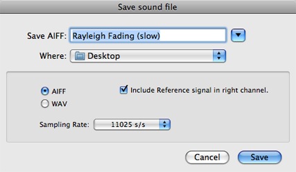
The default name for the sound file is the name of the HF
channel model. In addition to the usual file save dialog,
you can choose between AIFF or WAV format. (WAV is a
Windows format which the Mac OS can read and write.)
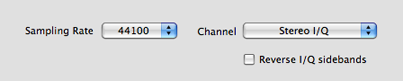
You can also select the sampling rate of the sound file.
11025 s/s is adequate for all bandwidths that cocoaPath
uses, and will create the smallest sound file, but you can
also choose 16000 or 44100 s/s if you need a rate to match
the needs of other applications.
Finally, there is a checkbox to select if you want to write
a single channel sound file or a stereo file. If you ask
for a stereo file, the right channel will contain a
time-aligned and noise-free reference signal that has no
ionospheric disturbance. This provides a signal with very
high signal to noise ratio that can be useful for automatic
detection of bit errors in the test channel when testing
modems.
When you select AIFF, cocoaPath will append the "aiff"
extension to the file name. If you choose WAV, cocoaPath
will append the "wav" extension to the file name.
3.2.1 Output Configuration
The Configuration button in the output section
opens the output configuration panel. You can close the
panel by using either the window's close button (the button
at the top left corner of windows), or by clicking again on
the Configuration button.
The output configuration panel allows you to select sound
card and sound card parameters for the output play through.
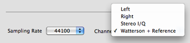
The output from the Watterson model can be sent to either
the left or the right channel of the sound card.
You can also select between two variants of two-channel
(stereo) output.
When you select Stereo I/Q, the in-phase component
of the Watterson analytic model is sent to the left channel
of the sound card, and the quadrature component of the
model is sent to the right channel. This allows you to
modulate the quadrature sampling exciter (QSE) of a
software defined radio (SDR). In conjunction with a QSE,
cocoaPath can be used to quantify the performance of
built-in digital mode decoders in HF receivers.
When Stereo I/Q is selected, the quadrature component can
be negated to reverse the sideband (whether the output
spectrum is higher or lower than the local oscillator) of
the QSE, as seen below:
You can select stereo output
where the Watterson model is sent to the left channel of
the sound card, and a time-aligned and noise-free reference
that has no ionospheric disturbance is sent to the right
channel of the sound card, as seen below:
3.3
Propagation Model Interface
The following figure shows the Propagation
Model section of the cocoaPath user interface in greater
detail:
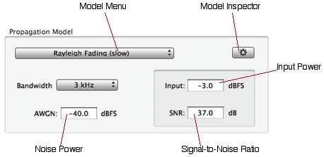
Figure 3.3-1 User
Interface for Propagation Model
The Model popup menu
selects one of the built-in Propagation models. As mention
in the Introduction, the propagation models are based on
the Watterson paper, with the addition of an additive noise
term that sets the signal-to-noise ratio of the model.
The power of the Additive White Gaussian Noise (AWGN) can
be set to an arbitrary decibel value relative to the full
scale value of an audio sample. The computations done
within cocoaPath do not saturate. However, when you output
the result to a sound file (or playing through to the
computer's speakers), the signal will clip at the full
scale value.
When an input signal arrives, the power is measured and
displayed in the Input Power box together with
signal-to-noise ratio (the ratio the input power and noise
power). Because sound files have a resolution of 16 bits,
setting the noise power to -96 dBFS will assure the output
is completely noise free.
The Model menu is grouped into ITU and CCIR conditions,
taken from Recommendation ITU-R F.1487 (Testing of HF
Modems with Bandwidths of Up to About 12 kHz Using
Ionospheric Channel Simulators) and Recommendation
CCIR 520-2 (Use of High Frequency
Ionospheric Channel Simulators).
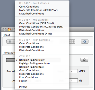
Figure 3.3-2 Propagation
Model Menu
Even though the ITU
recommendations are newer than the CCIR ones, the CCIR
conditions are included because the ITU recommendations
does not include the "flat fading"condition which consists
of Rayleigh Fading in the absence of multi-path.
When a CCIR condition overlaps an ITU condition, it is
called out in the ITU menu. This can be seen in the figure
above for the ITU Mid Latitudes Quiet Conditions,
which is marked as having the same parameters as the
CCIR Good Conditions.
As shown above, cocoaPath includes a built in "perfect"
propagation model (lack of Doppler spread and multipath)
that can be useful for evaluating modems using only
additive white Gaussian noise.
You can view and change the parameters of the selected
model by clicking on the Model Inspector button of
Figure 3.3-1 above. The Model Inspector window (Figure
3.3-3) should appear.
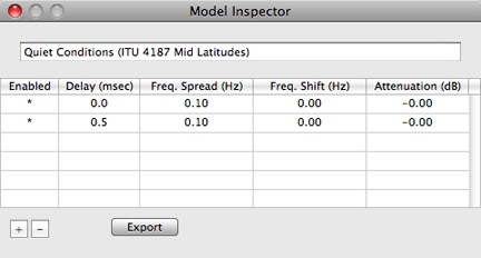
Figure 3.3-3 Model
Inspector
Each row in the table view of
the Model Inspector represents a Watterson path (read the
Technical section for more
details).
Each path is connected to a delay line tap in the model.
cocoaPath's time delay has a resolution of 0.0625
milliseconds and a maximum delay of 96 milliseconds. The
Doppler frequency spread, the Doppler shift and attenuation
determines the scattering function of a Watterson path. You
can temporarily disable a path by clearing the
Enabled cell of the path.
Although Watterson's models allow each path to take on a
different attenuation and Doppler Shift, none of the ITU
and CCIR conditions make use of these two parameters.
Because of this, the fading depth of a path as defined by
the ITU and CCIR documents can be unrealistically deep.
cocoaPath implements both attenuation and Doppler Shift
parameters, so you can use them to investigate more refined
propagation models. For example, adding a path that has no
relative delay and with no Doppler spread and attenuated to
some low level will limit the output from fading below the
level of this additional path.
3.4
Creating Custom Propagation Models
With the Model Inspector open, you can modify
any of the parameters of that model by clicking on the
table view cell and typing in new numbers. You can add or
delete paths by using the small + and - buttons that can be
seen at the bottom left of the Model Inspector window in
Figure 3.3-3.
The new model parameters will remain there until you
relaunch cocoaPath. When cocoaPath is relaunched, the
original ITU or CCIR model will be restored.
You can create permanent custom models by editing one of
the existing models, and then clicking on the
Export button in the Model Inspector window.
The title of the model (the text field at the top of the
Model Inspector) can be any text string. It is there for
you to place some meaningful explanation of the model. Note
that this title is not the name that appears in
the model menu.
When you click on the Export button, cocoaPath
will save the model to an XML format file. You can set the
file name itself to anything you wish; cocoaPath will add a
".model" file extension when it creates the file. The
filename you choose (without the extension) is the name
that will appear in the Model Menu when you import the
model.
Place your custom model inside the cocoaPath folder in the
Application Support folder of your home directory's Library
folder. You will need to create a new cocoaPath folder if
it is the first time you are adding a custom model.
Each time cocoaPath is launched, it will look in this
Application Support folder, searching for the cocoaPath
folder. Within the cocoaPath folder, the program looks for
files that have the ".model" file extension. If cocoaPath
finds one or more files with that extension, they may then
be imported.
Remember to relaunch cocoaPath each time you add a custom
model to Application Support. You can directly edit XML
files using the Dashcode application, the Property List
Editor, or TextEdit.
The custom model(s) will show up in the Model menu below
the built-in propagation models, as seen in Figure 3.4-1
below:
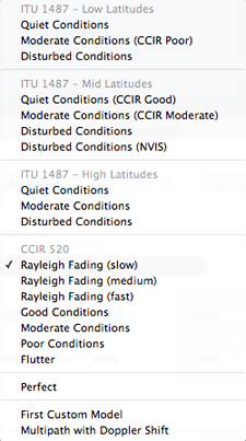
Figure 3.4-1 Model Menu
with Custom Models
3.4 Random Number Seeds
The random number generators that are used in
the cocoaPath models and AWGN noise source come from
separate routines, all of which execute the Wichmann-Hill
algorithm. The random numbers are not really completely random but are
generated from a set of linear congruence equations.
The linear congruences are initialized by an integer
"seed." cocoaPath maintains a single based seed is used as
a base to initialize the various random generators each
time you start the model by pressing Play. Each
generator is initialized with a different seed which are
fixed offsets from this base seed. All generators are
therefore independent, but of them will start from a known
state.
This is especially useful when comparing different modems
sequentially, since cocoaPath will send precisely the same
signal to all modems.
If you prefer to use a different starting seed, you can
change the base seed by selecting the Doppler Spread menu
item in the Main Menu bar.
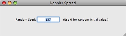
If you enter 0 in the seed
field, cocoaPath will use the current time as the seed --
which will cause the outcome to be completely random and
will practically never repeat.