The definitive definition of MFSK16 can be found here.
The block diagram for cocoaModem's MFSK16 demodulator is shown in Figure 1 below. This implementation allows the tuning to be off by as much as 50 Hz
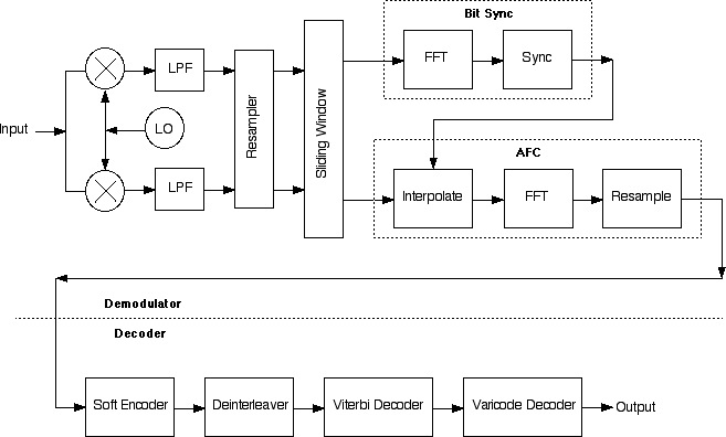
Figure 1 - cocoaModem
Demodulator/Decoder Block Diagram
Mixer
The input signal enters the demodulator
(-importArray: in the module MFSKReceiver.m) at a
sampling rate of 11025 samples/second. A quadrature mixer
is used to convert the signal to a low-passed analytic
signal using a quadrature local oscillator (LO).
The LO frequency is offset 125 Hz away the position the
user has clicked on the waterfall. This will approximately
center the MFSK16 signal in the output of the mixer around
DC.
If a lower sideband receiver is used, the spectrum of the
analytic signal is inverted by negating the quadrature term
of the local oscillator (i.e., the local oscillator "runs
backwards" in time).
Resampler
The output of the mixer goes through a pair of 200 Hz low
pass filters and the low-passed signal is then resampled to
a sampling rate of 500 samples per second.
This resampled low-pass signal is then buffered in a
sliding window (-newBuffer:: in the module
MFSKDemodulator.m).
At this sampling rate, each MFSK16 symbol is 32 samples
long. If a 32-point FFT is performed, each FFT bin would be
15.625 Hz wide.
The reason 500 Hz and 32 point FFT is chosen (instead of
250 Hz/16 point FFT) is so that AFC can be performed by
picking 16 out of the 32 bins rather than by adjusting the
local oscillator frequency. The latter would have to
account for the latency though the low pass FIR filter
pipeline.
Sync
For synchronization and AFC, 32 samples at a time is pulled
from the sliding window buffer and a 32-point FFT is
performed to the 32 samples. After each transform, the
window is advanced by four samples (the length of 1/8 of a
symbol) and another 32 point FTT is performed, and so on.
For each transform, the bin with the largest power is
extracted. These values are then formed into a time
sequence.
This time sequence reaches a maximum when the 32 samples
from the sliding window is perfectly time aligned to the
symbol. The reason is that when the 32 data points are not
aligned to the symbol clock, the energy of the tones will
be spread between two bins and each bin will not have as
much power as an FFT bin that is extracted from perfectly
aligned data.
The time sequence is oversampled by a factor of 4 (remember
that we had only performed one measurement per 4 samples
from the sliding window) and then passed through a comb
filter that is 11 symbol times wide. The comb is set to
have a period that correspond to the symbol period. The
output of the comb filter identifies which 32 samples from
the sliding window is properly time aligned with the MFSK16
symbol.
This time aligned 32 temporal data (analytic signal) is now
passed to the AFC stage.
AFC
When the AFC stage receives the 32 data points, it zero
fills the array into a 512 point array and performs a 512
point FFT to it. This gives a frequency resolution of 1/8
of an MFSK16 frequency bin. The output of the 512-point FFT
shows the sin(πx)/x profiles of each of the "original"
bins.
The 512 point FFT output is now searched for a global peak.
The peak identifies the true center of an MFSK16 bin. This
offset is chosen to resample the 512 bins into 32 bins. The
central 24 of these resampled bins are then passed to the
next stage.
Bin Identification
The sixteen MFSK16 bins should be within these 24 bins.
24 bins are picked instead of 16 bins to allow for the user
not clicking precisely on top of the base MFSK16 tone. This
allows the original local oscillator frequency to be off by
up to plus or minus 4 MFSK16 frequency bins.
Over a period of time, by accumulating a histogram of bins,
we can identify the most likely 16 (contiguous) bins out of
the 24 bins to be the MFSK16 vector. The power in these 16
bins are passed on to the decoder section of the modem.
Soft Encoder
Every 15.625 seconds, a new vector of 16 floating point
numbers arrives at the soft encoder (-softEncode:
in MFSKDemodulator.m). The soft encoder encodes the 16
frequency bins with a 4 bit index.
If it were a hard encoder and the input has good signal to
noise ratio, the result would just be a 4-bit index of the
largest of the 16 tones.
MFSK16 uses a 4-bit Gray code instead of a 4-bit radix
weighted radix code ("regular binary" numbers), and the
conversion to Gray code is done in this step in
cocoaModem.
cocoaModem uses a soft decoder rather than a hard decoder,
so that the 4 "bits" are actually four floating point
numbers whose value lie between 0.0 and 1.0.
The 16 input bins are first converted into probabilities.
The first step is to apply a power of 1.35 to each of the
sixteen values. The factor of 1.35 is arrived empirically
for best decoding within white Gaussian noise.
These sixteen adjusted values are then normalized so their
sum come out to be 1.0. I.e., each bin is now equated with
a probability that the original vector was in the
corresponding bin.
The least significant result "bit" is them just the
accumulated probabilities of the odd bins. The next
significant "bit" is just the accumulated probabilities of
bins whose index has the next to least significant bit
turned on. E.g.,

In the above, mappedVector is the array of the
sixteen floating point values that have been remapped by
the Gray code and renormalized into probabilities (i.e.,
the sum of mappedVector values is 1.0).
Deinterleaver
MFSK16 calls for a 10-stage diagonal deinterleaver to be
used to unscramble the input data. Each diagonal
deinterleaver is a 4-by-4 array. However, as we show
here, the ten diagonal
deinterleaver stages is mathematically equivalent to a
single linear deinterleaver that is 160 elements in
length.
The four floating point numbers from the Soft Decoder are
inserted into the deinterleaver each 1/15.625 seconds, and
four floating point numbers are pulled from the
interleaver.
The four output of the deinterleaver are grouped into two
soft dibits (bit pairs) and handed one at a time over to
the (soft) Viterbi decoder for the convolutional code.
Viterbi Decoder
On transmission, MFSK16 uses two 6th order convolutional
codes to encode each bit into a dibit. The generator
polynomials for the two code streams are
![]()
![]()
![]() and
and
![]()
![]()
The receiver's task is to determine the most likely bit
that was transmitted for a dibit that the deinterleaver has
handed to us.
cocoaModem uses the Viterbi algorithm to find the most
likely bit that was transmitted from the dibits. The
Euclidean distance between the soft dibit from the
deinterleaver and the hard dibit from the convolutional
code is used as the error estimate for the path metric
of the a trellis state of the Viterbi decoder.
cocoaModem has a switch that allows the user to select
between short latency (reduced error correction when the
SNR is good), where we use the path metric from the first
stage of the trellis and high latency (better error
correction) where we use the path metric for the 45th stage
of the trellis.
Varicode Decoder
The bits from the Viterbi decoder are accumulated as a bit
string until a 001 pattern is seen, where upon the codeword
(without the trailing 1) is finally sent to a table lookup
that decodes the bit string into an ASCII character.