
cocoaFilter
Kok Chen, W7AY [w7ay (at)
arrl (dot) net]
Last updated: November 19, 2010
Introduction
cocoaFilter is a CW audio peak filter (APF) for Mac OS X.
The application takes audio from a transceiver though an
input sound card, applies a bandpass filter that has an
adjustable center frequency and Q (or bandwidth), and
passes the signal to an output sound card, which can then
be fed to speakers or a pair of headphones.
cocoaFilter requires minimally Mac OS X 10.6 (Snow Leopard)
to run in. The application can be downloaded from here.
Double click on the downloaded Disk Image (dmg) to open the
volume, and drag copy the cocoaFilter application to your
Applications folder. The dmg file also contains a settings
file (cocoaFilter.pmset) to control cocoaFilter from a
PowerMate (the PowerMate installation
procedure described below in the Main Window
section).
cocoaFilter is completely free and is not a supported
program. I wrote it to experiment with a few ideas. If you
have other ideas, the Objective-C sources for cocoaFilter
are in the Xcode project for further experimentation. See
the section that describes technical details further down.
Preferences
The sound cards are selected in the cocoaFilter Preference
panel.
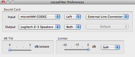
You can choose either the left or the right channel of an
input stereo sound card. You can choose to send the output
of cocoaFilter to the left, right or both channels of the
output sound card. cocoaFilter only supports the first two
channels of a sound card that contains more than 2
channels. The channels popup menu is grayed out for sound
cards that contain only a single channel (e.g., an Apple
iSight).
Sound cards may have multiple sources. The input sound card
in the figure above is multiplexed between a microphone
input and a line level input, for example, and the
rightmost set of sound card popup menus is set to select
the line input. Be sure to set the menu to what you have
wired the sound card for. For sound cards that contain only
a single source, the source menus will be grayed out,
showing a Default menu item, and no source
selection needs to be made.
So as not to affect other applications that cocoaFilter is
sharing a sound card with (e.g., cocoaModem), cocoaFilter
neither sets nor changes the sampling rate of a sound card.
cocoaFilter will adapt to the sampling rates that other
applications have chosen. Please read the later IIR
Filter section on preferred sampling rates. If you
want to change the sampling rate, you can use the Mac OS X
"Audio MIDI Setup" utility that is in the Utilities folder
of the Snow Leopard Applications folder.
As seen in the above figure, cocoaFilter has a limiter that
clips at a level which is adjustable down to 20 dB below
the full scale of the output sound card. The limiter can
apply hard clipping or soft clipping (shown above) or be
turned completely off.
(See section "IIR Filter" below for a description of the
IIR Tilt parameter in the Preference panel.)
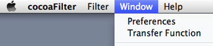
The Preference panel is opened by using the
"Preferences..." menu item in cocoaFilter's main menu (just
to the right of the Apple menu in the main Menu Bar). The
Preference panel can also be opened from the "Preferences"
menu in cocoaFilter's Window menu in the main Menu Bar:
Plist
All parameters from Preferences panel, plus filter
parameters, window positions, etc, are saved to a plist
when you exit cocoaFilter. The cocoaFilter plist is a file
in the Preferences folder of your home directory's Library
folder with the name w7ay.cocoaFilter.plist. This is the
only file that is created by cocoaFilter. The plist file is
in XML format and can be opened with a text editor or the
Mac OS X Property List Editor.
Main Window
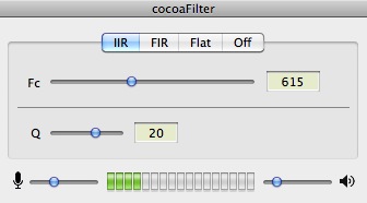
The main cocoaFilter window contains the controls and means
of selecting filters. By using the tabs, you can select
between an IIR (infinite impulse response) filter, an FIR
(finite impulse response) filter, a flat filter (input is
pass to the output with no filtering) or to turn output
sound off completely (sampling stops, and effectively
muting the output from cocoaFilter).
The two filters are discussed in detail in the IIR
Filter and FIR filter sections below.
Like all Mac OS X sound applications, the cocoaFilter's
output is mixed with the output of other applications
before it is sent to the sound card. If iTunes is playing
to the sound card, for example, cocoaFilter's output will
be mixed with it.
Separate attenuation sliders for the input and output sound
cards are at the bottom of the main cocoaFilter window. A
"VU Meter" in between the two sliders
measures the peak input to warn of any clipping of the
input sound card.
Please note that the values of these attenuators are also
shared with other applications. For example, if iTunes is
using the same output sound card, the cocoaFilter output
slider will also affect the output volume from iTunes.
However, the input slider in cocoaFilter will not affect
iTunes output. Neither controls will affect iTunes if the
latter application uses a different output sound card than
cocoaFilter. Likewise, if the input sound card is shared
with cocoaModem, the cocoaFilter slider will affect the
input level cocoaModem receives from the sound card.
When lit, the rightmost two bars of the "VU Meter" will
appear as yellow and red bars. You must
keep the input slider set to a low enough position so that
the yellow and red bars never appear. If the input sound
card clips, the filters will no longer be linear -- at
which point, they no longer behave like bandpass filters,
and the output from cocoaFilter can become severely
distorted.
Some A/D converters do not come with adjustable digital
attenuators. In these cases, the cocoaFilter slider will be
grayed out, and you will need some other (e.g., analog pot)
methods to keep the input sound card from clipping.
The center frequencies of the IIR and the FIR filter are
locked to one another. When you change from an IIR to an
FIR filter (and vice versa), the new filter takes the
center frequency from the filter you just left. The center
frequency can be varied between 300 Hz to 1100 Hz.
The IIR filter has adjustable Q that is between 1 and 30, and the
FIR filter has adjustable -10 dB bandwidth that is
between 20 Hz and 300 Hz.
The center frequency of the IIR and FIR filters can be
adjusted by
- using the Fc sliders in the main window
- directly typing the frequency into the Fc text field
- using the scroll wheel on the mouse
- using the left and right arrow keys on a keyboard
- using the knob of a PowerMate.
The frequency sliders are controlled by the mouse scroll wheel when either the main cocoaFilter window or the transfer function window is active. If you hold down the Command key on the keyboard, the mouse scroll wheel will control the Q of the IIR filter, and the bandwidth of the FIR filter.
You can speed up the keyboard and mouse scroll wheel tuning rate by holding down the Option key.
The left and right arrows on the keyboard can also be used to control the center frequency of the filters. The up and down arrow keys on the keyboard controls the Q of the IIR filter, or the bandwidth of the FIR filter.
The PowerMate gives the smoothest and most intuitive way for adjusting cocoaFilter parameters. To use a PowerMate, you will need to import the PowerMate settings file (cocoaFilter.pmset) that resides in the cocoaFilter disk image, into the PowerMate application. Simply drag and drop the file into PowerMate window's item list (as described here).
If you have a Griffin Technology PowerMate and have installed the cocoaFilter settings, knob rotation controls the center frequency. cocoaFilter looks at how fast you rotate the knob. Faster rotation will change the frequency by a larger step. If you press the knob down towards the table, and rotate the knob, the PowerMate controls the Q or the bandwidth of the filters.
Transfer Function Window
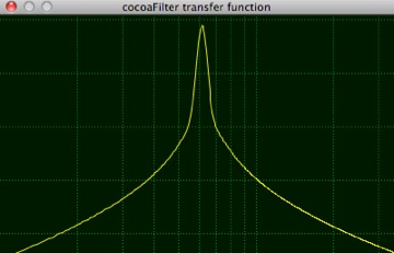
The filter response of the currently selected filter can be viewed in the transfer function window. The transfer function display changes in real time as you adjust filter parameters, so you can get an instantaneous graphical view of the filter response.
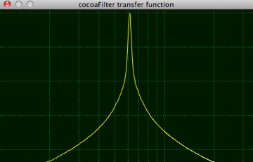
The transfer function window is opened by selecting the Transfer Function menu item in cocoaFilter's Window menu. The vertical dashed green markers show a log scale of frequency. The left edge of the transfer function plot represents 100 Hz and the right edge of the plot represents approximately 3200 Hz. The rightmost vertical line that appears in the plot is located at 3000 Hz.
The vertical scale is shown by horizontal dashed lines that are separated by 10 dB. The topmost line show in the plot represents a +10 dB gain. The next line down represents 0 dB gain, etc.
The plot above shows the response of the IIR filter with center frequency set to 500 Hz and Q set to 20.
The transfer function window is closed by using the red close button at the left of the window's title bar. If the window was visible when you last quit cocoaFilter, it will automatically open the next time you launch cocoaFilter and positioned in the computer display where you had earlier left it.
The display updates when you switch between an IIR and an FIR filter.
IIR Filter
As mentioned earlier, an IIR filter is selected by selecting the IIR tab in the main cocoaFilter window.
The cocoaFilter IIR filter mimics the behavior of the traditional APF. The center frequency of cocoaFilter's IIR filter can be adjusted between 300 Hz and 1100 Hz and the Q can be adjusted between 1 and 30.
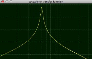
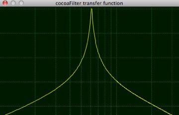
The following figures show the IIR at Q= 20, and center frequency set to 400 Hz (left) and 800 Hz (right).
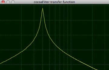
The gain of the IIR filter is increased slightly as the Q is increased, to a little more than 10 dB at a Q of 30. Even with this gain, the white noise floor is still monotonically reduced as Q is increased, but the gain for the actual centered signal increase gives a better psychoacoustic effect as the Q of the filter is increased.
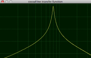
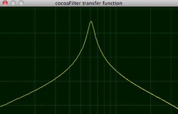
The following figures show the IIR with a center frequency of 615 Hz, and Q set to 10 (left) and 30 (right). Notice the gain boost.
In addition to the center frequency and Q adjustments, up to about 3 dB/octave of spectrum "tilt" can be applied to the IIR filter (in the Preference panel). This lets you tailor the noise spectrum when the Q of the filter is low. The audible effect is minimal when the Q is raised to 30 but the "color" of the noise is quite evident at a Q of 1 and a tilt might sound more pleasant sounding to some.
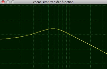
A tilt of 0 gives the traditional symmetrical bandpass, and a tilt of 3 dB/octave ("pink noise") suppresses the higher frequencies at the cost of raising low frequency noise. (A side note: the APF of the Yaesu FT-1000D, arguably the best APF known, is not symmetric but has a slight passband tilt.)
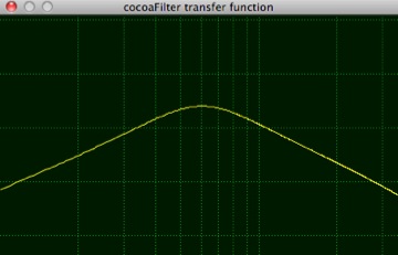
The following figures show the IIR filter transfer functions with a Q of 1. The left figure has a 0 dB tilt of a symmetrical bandpass filter, and the right hand figure shows a tilt of 3 dB/octave (more obvious at lower frequencies). (The FT-1000D has a tilt that is not as severe as the 3 dB/octave shown in the figure on the right.)
The IIR filter coefficients are computed on-the-fly when you change the center frequency, Q or tilt of the filter. The filter design uses the bilinear transform methodology to model an analog filter and it requires the sampling rate to be much higher than the filter passband to obtain an accurate digital representation. You can watch the transfer function change when you change the sampling rate. In general, using an input sampling rate of 8000 samples/second will produce a filter that looks a little different (and also sound a little different) from using 16000 samples/second. The second order filter appears to converge after 32000 samples/second, and you should notice only small differences between using 32000, 44100 or 48000 samples/second. There is no reason to go beyond 48000 samples/second for this type of application.
The easiest way to adjust the sampling rate is through the application Audio MIDI Setup in the /Application/Utilities folder of Snow Leopard. You can also change the sampling rate by using an application such as cocoaModem.
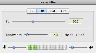
FIR Filter
The second filter in cocoaFilter is an FIR (finite impulse response) filter. Unlike traditional FIR bandpass design that has a flat top which generally determines the bandwidth of the filter, cocoaFilter's FIR is designed as an infinitesimally narrow filter, but using wider than usual "transition band" (the digital equivalent of the "skirt" of an analog filter). The equivalent noise bandwidth of the filter is therefore determined from the filter's window, not from the non-existent flat top passband.
The following figures show the FIR filter transfer functions with a center frequency of 615 Hz, at a bandwidth of 20 Hz (left) and 40 Hz (right). Notice the purposely "flared" response and a lack of flat top when compared to traditional FIR bandpass filters. But unlike the IIR case, notice that the "flaring" does not start from as high level as in the IIR case.
The reason for picking a transfer function above is to experiment with a conjecture of mine that even though a narrow filter for both signal and noise is optimal in the least squares sense, it is perhaps harder for the human ear-brain system to copy a carrier if the noise spectrum is too similar to the spectrum of the carrier. This could explain why analog audio peaking filters are much better for aural copy of Morse than very narrow FIR filters.
The noise spectrum of the cocoaFilter FIR filter is purposely broadened (but at levels below -20 dB) to give the noise a different characteristics than the signal. Total noise power is not increased significantly, but the noise "color" is aurally different from a narrow bandpass noise.
For the same 10 dB bandwidth, this type of transfer function also appears to produce a filter that is less "hollow sounding" or "DSP sounding" than the typical narrow flat topped bandpass filter. The bandwidth of the FIR filter in cocoaFilter can be set to between 20 Hz and 300 Hz at the -10 dB points. Filter gain is also increased slightly as the filter becomes narrower.
If you program in C, I encourage you to take the Xcode project to experiment further (see below).
Technical details
The Xcode project is available from the link in the download page.
The cocoaFilter sources can be used as a simple and compact platform for implementing other filters, or for implementing signal generators and modems that require sound card input and/or sound card output.
My primary aim of writing cocoaFilter is to investigate some ideas (e.g., an FIR filter that mimics a high-Q IIR filter, but with a lower filter skirt), but a secondary aim is to provide a project/framework so others can easily modify the code to do further experiments without having to bother with audio or graphics programming.
The existing IIR and FIR filters in cocoaFilter can be very easily modified to support other transfer functions.
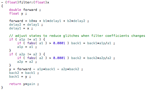
IIR Implementation
The following shows the -filter method in the IIR filter. (cocoaFilter is written in Objective-C, but it should be easily understandable if you already know C). The filter in cocoaFilter accepts one floating point argument and returns one floating point output value:
The IIR filter in cocoaFilter is based on a second order variable Q bandpass filter,

The s-plane transfer function
H(s) is converted into a z-plane transfer function H(z)
using the bilinear transform and normalized to
the sampling period (the sampling rate is taken care of
by the application):
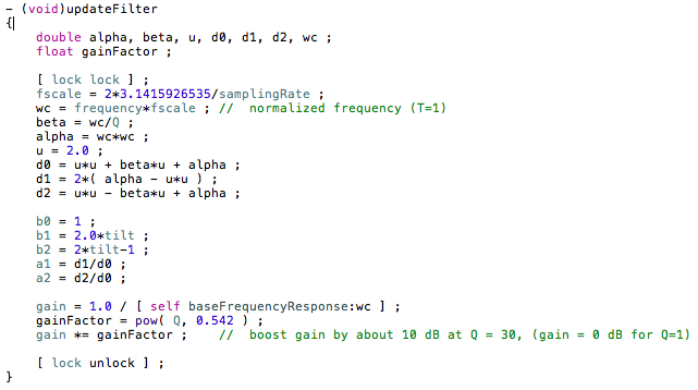
Whenever a user interface parameter such as center
frequency or Q of the IIR filter changes, the application
calls the -updateFilter method above. This recomputes the
z-plane poles (a[i]) and zeros (b[i]) which are then used
in the -filter method.
You can therefore alter the behavior of the default 2nd
order IIR filter by just changing the -updateFilter method
in IIR2.m. If you change it to a higher order filter, you
would need to change the array allocation in the header
file and modify both the -updateFilter and the -filter
methods.
Notice that the spectral "tilt" is created by applying a
homotopy between a pure bandpass (a
symmetrical filter with a zero at z=0) filter and a
lowpass filter (no zero at z=0, with a spectral peak at
Fc when Q is high).
FIR Implementation
The -updateFilter method in the default FIR filter in
cocoaFilter looks like this:
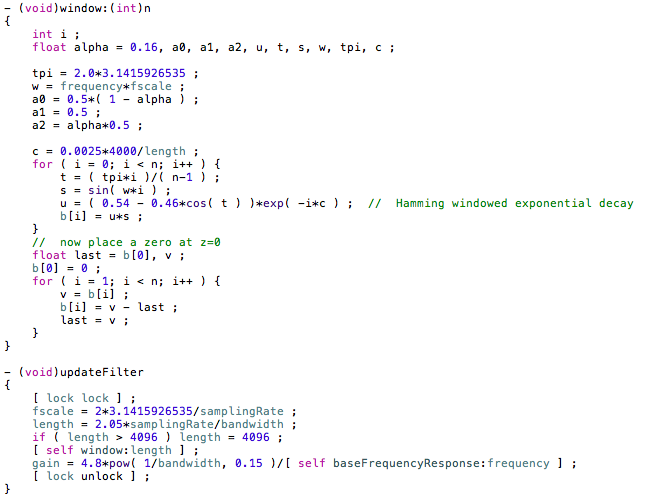
This FIR design is not phase linear (notice the exponential
decay of FIR coefficients). It also has an extra zero
placed at z=0. This mimics the general shape of a
symmetrical IIR bandpass filter, but has a lower "skirt"
than the IIR filter.
Transfer Function Plots
IIR2.m and FIR.m are subclasses of the Filter.m class.
In addition to -filter and -updateFilter methods of
Filter.m, you can provide a method to supply the filter
spectral transfer function for the application to draw the
plot in the transfer function window. This is not
mandatory, but can be quite useful as a visual aid.
For example, the transfer function for the default IIR
filter is very simply defined (i.e., using z =
jωT)
as:
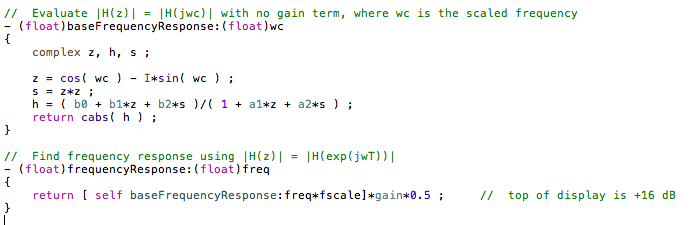
The application calls -frequencyResponse for each frequency
it wants to plot. You supply the value and all the plotting
is done for you automatically.
There is no restriction on how you can use the source code
in the Xcode project. No GPL source is present in
cocoaFilter and you are free to take pieces of the code or
use cocoaFilter as the platform to build other filters,
generators or modems, to build your own applications
without having to republish your sources. I simply request
that you pay it forward if you include a piece of
cocoaFilter code into a GPL body of code by placing an
exclusionary note that the cocoaFilter part is free of GPL,
so other people can continue to use it freely in a similar
manner that you had.