FSK Sidebands
Kok Chen, W7AY
Oct 23, 2005
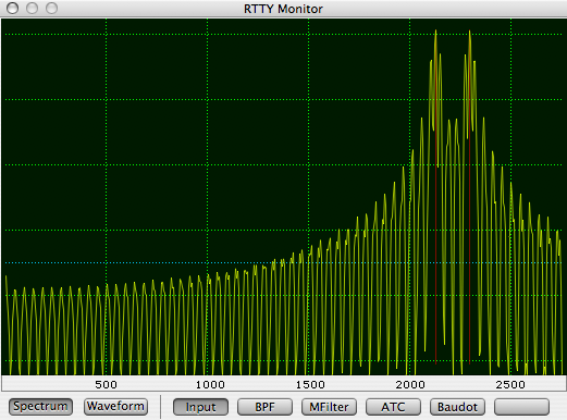
45 baud, 170 Hz shift FSK Spectrum -- the figure above shows an FSK signal that is generated by switching between two free running oscillators. The horizontal scale is shown in Hz below the spectrum. The vertical is logarithmic, each horizontal green line represents a 10 dB change (note that this plot is not the usual cocoaModem display, which uses 20 dB per horizontal line).
This short term spectrum is taken from a 185 ms frame of an RYRY (1.5 stop bits) sequence which bounces around quite a bit from frame to frame. Each frame is obtained from a Blackman windowed FFT of length 2048, at a sampling rate of 11025 s/s. It represents slightly over one character’s worth of transmission.
The red vertical lines are markers placed at 2125 Hz and 2295 Hz.
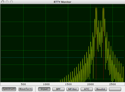
Phase continuous FSK -- the above figure shows FSK that is generated with a phase continuous generator. This type of signal will still show a first order (slope) discontinuity, but there is no zeroth order discontinuity (i.e., the voltage does not jump levels at bit boundaries), hence the much narrower signal.
Even though it is much better than the non-phase continuous case, the first order discontinuities still occupies more bandwidth than neccessary to carry the information.
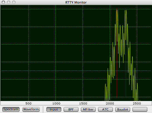
Wave-shaped continuous phase FSK - in addition to using continuous phase switching, this FSK signal is generated by passing an audio FSK (AFSK) signal through a bandpass filter whose 3 dB points are approximately out the seventh harmonic of the basic modulation signal of a 45 baud keying signal (7 times 22.7 -- 22.7 being half of 45.45 Hz).
The bandpass filter is a Blackman windowed sinc symmetric FIR with 128 taps.
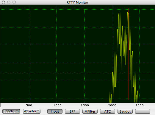
More severe wave-shaping continuous phase FSK - the FIR bandpass filter’s passband is set to the 3-rd harmonic of the keying signal.
Notice that the spectrum has narrowed by a significant amount from the case where wave shaping is not applied. The sidebands have fallen to 35 dB below the mark and space carriers when they are more than 200 Hz away from the mark and space carriers. This signal occupies a little over about 3 times the width of the FSK shift (170 Hz).
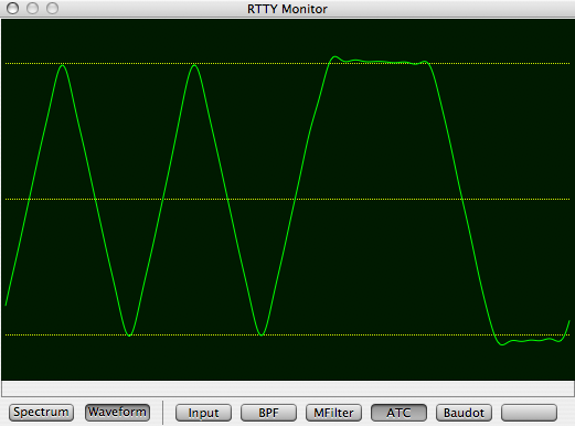
Matched Filter output from an FSK demodulator -- cocoaModem uses a true matched filter on the mark and space signals and this waveform shows the signal formed from the difference of the two matched filter outputs.
In this case, the signal that is fed to the demodulator is a continuous phase FSK signal.
The matched filter is implemented as an FIR with a stepped response which is 22ms wide, matching the bit period of a 45 baud RTTY signal. A small portion of the leading and trailing edge of the pulse where a raised cosine profile is used to soften the pulse slightly.
An ideal FIR matched filter will have a perfect triangle shape when an alternating bit pattern is received. The data bits are sampled at the peak of the triangles.
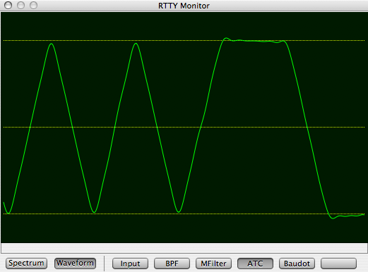
Matched filter output from a wave-shaped AFSK signal -- this is the same signal as the above but the FSK signal is generated by bandpassing an AFSK signal using the 7-th harmonic filter mentioned earlier.
Notice the slight reduction in the peaks of the triangles. This will cause the demodulator to throw more error bits. However, with this slight difference seen here, it would give an unnoticeable performance difference when compared to a signal where no wave shaping is done.

Matched filter output from a more severe wave-shaped AFSK signal -- the same phase continuous signal is passed through the bandpass filter with cutoffs at the 3rd harmonic of the keying signal.
Notice that the matched filter output is now reduced significantly. The signal to noise ratio would have to be about 1.5 dB better than the unfiltered phase continuous FSK signal for it to print as well.