Automatic Threshold Correction (ATC) is used in frequency shift keyed (FSK) reception to optimize the decision threshold level in the presence of selective fading.
With On-Off Keying (OOK), a single carrier is keyed on and off to convey information. OOK can suffer from Rayleigh fading on HF propagation channels.
Frequency Shift Keying (FSK) synchronously keys two separate carriers (when one carrier is off, the other carrier is on) and has on average 3 dB better sensitivity than OOK. To produce the same error rate as FSK, OOK would need to transmit twice the peak power as does FSK.
One of the carriers of FSK is called the Mark carrier and the other carrier is called the Space carrier. The separation of the carriers is called the FSK “shift.”
An additional (and very important) advantage of FSK is that selective fading often occurs in HF channels. If the FSK shift is sufficiently wide, one of the FSK carriers can remain strong while the other carrier undergoes a deep fade. Unlike OOK, this allows the FSK signal to still be copied through selective fading, albeit at a higher error rate than when both FSK carriers are strong.
FSK Demodulation
The information bits of an FSK signal are usually demodulated by subtracting the amplitude of the filtered Space signal from the amplitude of the filtered Mark signal, with the decision threshold set to zero. When the difference is greater than zero, a Mark is assumed to be sent. If the difference is below zero, a Space is assumed to be sent. This process is often called slicing. For optimal demodulation of a bit stream in additive white Gaussian noise (AWGN), a matched filter can be used in the Mark and Space filter locations. A matched filter can also be placed just ahead of the slicer.
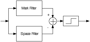
Simple FSK Demodulator.
Automatic Threshold Correction (ATC)
When selective fading attenuates either the Mark tone or
the Space tone so that their envelopes are no longer equal
in strength, the use of a simple FSK demodulator with a
fixed slicing level at zero is no longer optimal. Frerking
in Digital Signal Processing in Communication
Systems (ISBN 0-442-01616-6) has a detailed analysis
of an Automatic Threshold Correction (ATC) circuit as the
Mark signal undergoes a deep fade.
The usual form of an ATC is created by adding a pair of
Fast-Charge-Slow-Discharge envelope detectors
(shown in the figure below as boxes labelled ENV). These
are used to track the amplitude of the envelope as it
undergoes a fade, very much like fast-charge-slow-discharge
circuits in AGC implementations.
With digital implementations, it is very easy to delay the
actual signals relative to the ENV stages so you can look
ahead at the “future” trend of the signal amplitude. At the
expense of a lag of a few characters, better estimates of
the Mark and Space envelopes can be obtained.
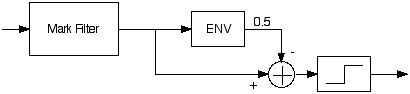
As seen in the following figure, one half of the envelope
detector voltages are subtracted from the Mark and Space
signals. As one of the two FSK tone pairs fade, the
envelope values become unbalanced and biases the slicer
threshold toward the midpoint of the Mark and Space peaks.
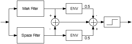
Automatic Threshold Correction (ATC),
Notice that when the Mark
signal fades completely away, the envelope voltage
associated with the Mark signal also vanishes, and the ATC
is basically decoding the FSK signal with a Space-only
demodulator whose slicer threshold is set to one half of
the amplitude of the Space envelope.
Care should be taken to ensure that either the Mark and
Space filters don't have appreciable overlaps (or
additional filters placed ahead of the envelope filters),
otherwise the derived threshold value could be biased
towards the weaker of the two signals.
ATC Problem
The ATC automatically turns the demodulator into a
Mark-only demodulator when the Space signal fades
completely away, and it automatically turns the demodulator
into a Space-only demodulator when the Mark signal fades
completely away.
In between these two extremes, the ATC sets an unbiased
slicer threshold that accounts for the difference in
amplitudes of the Mark and the Space signals.
At all signal levels and selective fading instances, the
ATC schematic that shown in the figure above provides the
optimal slicing threshold for an FSK signal.
Upon close inspection, however, there is a problem with the
ATC circuit shown. While the decision threshold may be
optimal, the signal to noise ratio (SNR) is not optimal. I
had accidentally stumbled upon this while investigating
better methods for extracting envelopes of the Mark and
Space components of FSK signals.
Notice that when the Space signal has selectively faded,
the noise (either sky noise or receiver noise) still
arrives through the Space filter, and the ATC circuit can
be reduced to the figure below. Mark+noise enters the Mark
filter, but only noise enters the Space filter.
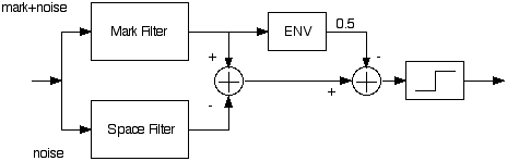
ATC Under Mark-only Condition.
Compare the above figure to a
true Mark-only demodulator, shown below.
Mark-Only Demodulation.
In the ATC circuit, the noise
contribution from the Space channel remains even when the
Space signal has completely faded away. In the absence
of a Space signal, the ATC circuit therefore has on average
about 3 dB more noise than the Mark-only circuit, if the
noise in the Mark and Space channels are uncorrelated.
Because of this, in the presence of selective fading, the
traditional FSK demodulator with or without ATC, will
always have a degraded signal to noise ratio when one of
the channels has only partially faded away, reaching a 3 dB
deficit from an optimal demodulator when one of the
carriers has faded completely away.
Under selective fading, the simple FSK demodulator without
ATC suffers additionally from having the wrong slicer
threshold.
SNR-optimized Demodulator for Selectively Fading
Channels
We can remove the noise contribution from a
channel that is under a severe selective fade by applying a
gain term after the Mark and Space filters.
Given uncorrelated noise in the Mark and Space channels,
when the amplitude of the envelope of space signal is
attenuated by a factor k due to selective
fading, the SNR at the decoder is proportional to

where µ is the gain that is applied after the space filter.
It can be shown that the maximum SNR is achieved by making
µ = k.
Using this, a SNR-optimized
threshold-corrected FSK demodulator is shown in the
following figure.
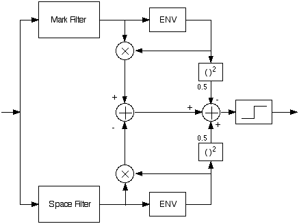
SNR-optimized FSK Demodulator for Selectively Fading
Channels.
As before, each of the ENV
blocks in the above figure measures the amplitude of the
envelope of the input mark or space streams.
Notice that the mark and space filter outputs in the above
figure are multiplied by a gain factor before they are
sliced. As we had mentioned earlier, the optimal gain is
achieved by multiplying the mark and space signals by the
amplitude of their own envelopes. Thus the gain terms are
simply the output from the envelope detectors.
When the envelope of a channel drops by a factor of
k, for optimal SNR, we further attenuate
it by yet another factor of k. Thus, a
channel that has selectively faded by a factor of
k will move the optimal slicer threshold
(the rightmost parts of the above figure) by a factor of
one half of the square of k, as shown
above.
With this algorithm, when the space signal fades to zero
due to selective fading, the output of the space filter
would be reduced to zero before it is subtracted from the
mark signal. As a result, the noise from the space filter
is also attenuated to zero. Indeed, this new demodulator
looks precisely like a Mark-only demodulator when the
envelope of the Space channel falls to zero.
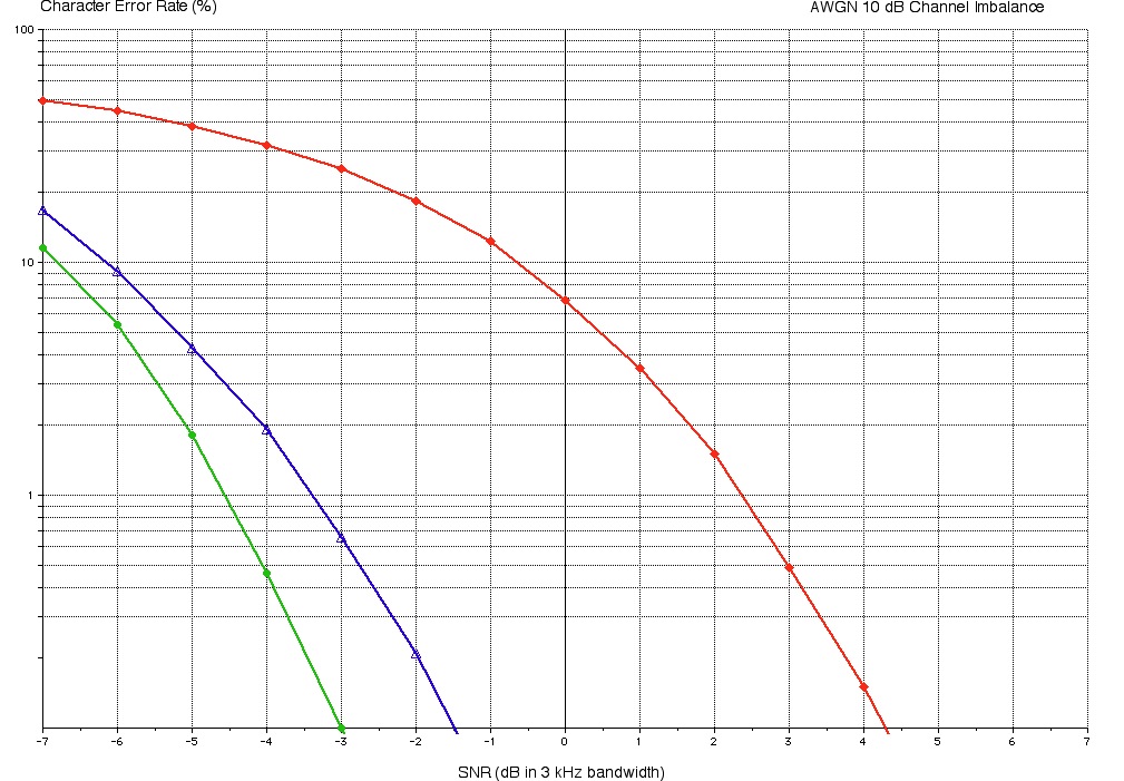
Performance
The following is a plot of Character Error
Rate (CER in percentage of character errors) versus
signal-to-noise ratio (SNR) for the case of a noisy
non-fading channel where the mark and space carriers are
imbalanced by 14 dB (to simulate sustained selective fading
where one of the carriers has faded by 14 dB).
The noise bandwidth is 3 kHz. For a 300 Hz noise bandwidth,
add 10 dB to the horizontal scale.
The characters are clocked from a perfect clock; only bit
errors are measured here -- errors due to start-stop
synchronization is ignored.
The red curve (filled diamonds) is the CER of a simple
slicer. The blue curve (open triangles) is the CER of a
slicer using traditional automatic threshold correction
(ATC), and the green curve (filled circles) is the CER for
the improved ATC that was explained above.
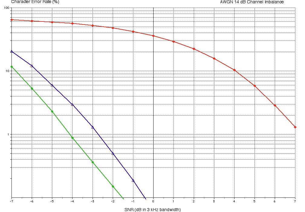
The difference in the red and blue curves shows why the use
of an ATC is important. In this case (a difference of 14 dB
between Mark and Space carriers), it can be seen that with
a SNR of about -2.8 dB, the ATC based demodulator has an
error rate of 1% while the simple slicer has more than 50%
errors. The green curve (the improved ATC) gives an
additional improvement, yielding the same error as the
straightforward ATC with a 1 dB to 1.5 dB worse SNR.
The following plot shows the same curves for the case where
the difference between Mark and Space carriers is 10 dB.